12
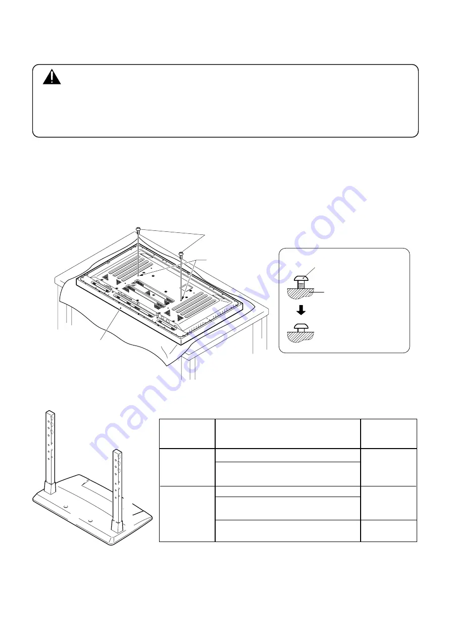
Stand attaching to the Plasma Display
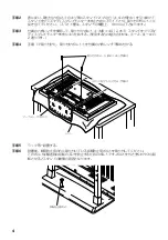
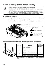
1. Place a sheet or protective cover to protect the display from scratches or damage.
2. Assemble only with the plasma display lying flat on a table or similar surface.
3. Insert the bolts vertically in the holes and tighten them, but do not apply excessive pressure that tightens them
more than necessary.
4. Move the stand so that the stand screw holes and the nuts that connect the main display line up correctly.
5. The display is a 50” model that weighs approximately 40 kilograms (88 lb) and has little depth, making the
display very unstable. For this reason, at least two people are required for setup and installation.
Notes
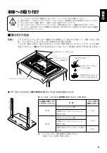
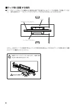
Installation bolt
1
Plasma display
Stop screwing down the
bolt when the threads are
no longer visible.
Holes "a"
(holes in center of
plasma display)
Plasma display housing
Installation bolt
1
(M8 x 20)
7
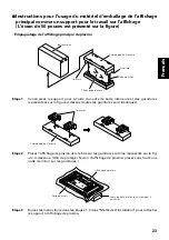
Installation Method
Step 1.
With the plasma display lying flat, insert and secure the two Installation bolts
1
(M8 x 20)
in the holes "a" located in the plasma display housing.
At this point, tighten these bolts
1
only until the threads are no longer visible when
viewed from t he side (you will be unable to attach the display if the bolts are screwed in
completely).
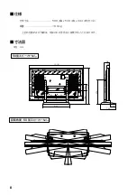
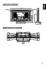
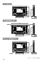
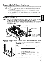
Regarding the stand pipe screw holes when the stand is used as a desktop stand
C
B
A
C
´
B
´
A
´
B
A
C
´
B
´
A
´
C
Table: Stand pipe screw holes when the stand is used as a desktop stand
Plasma display
model
Without optional speakers
With optional speakers attached to both sides
of display
B
,
B
'
50"
Specifications
Screw holes
used with stand
orientation
Without optional speakers
With optional speakers attached to both sides
of display
With optional speakers attached at bottom of
display
Note:
Screw holes
C
and
C
' are not for routine use. (They are used for separately sold
options.)
43"
A
,
A
'
B
,
B
'
Summary of Contents for PDK-TS03
Page 83: ......

