background image

7

Ja

日本語

2006パイオニア株式会社 禁無断転載

仕 様

外形寸法

576 mm (幅)× 491 mm (高さ) × 335 mm (奥行き)

質量

5.9 kg

・上記の仕様および外観は、改良のため予告なく変更することがあります。

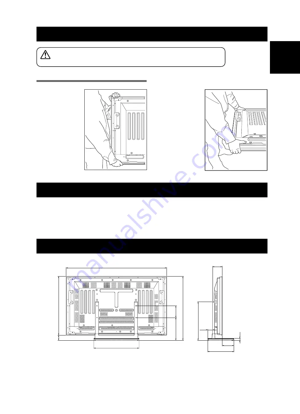
寸法図

単位:mm

ラックなどに設置する場合

ラックなどに設置する場合は、

必ず2人でプラズマディスプレイを持ってください。

プラズマディスプレイ
を立たせて持つ場合

プラズマディスプレイ
を寝かせて持つ場合

プラズマディスプレイの持ち方

注意

576

1282

149.4

750.5

65

491

335

25

62.5

123.1

815.5

150.5

289.5

Summary of Contents for PDK-TS23

Page 1: ...uctions Mode d emploi Bedienungsanleitung Istruzioni per l uso Gebruiksaanwijzing Manual de instrucciones テーブルトップスタンド Table top stand Pied de table Tischständer Supporto di tavolo Tafelbladstaander Soporte de mesa PDK TS23 ...

Page 2: ...弊社製プラズマディスプレイ PDP 5000EX 専用 のテーブルトップスタンドです その他の機器への取り付けに関しては対応しておりません 詳しくは お買い求めの販売店にご相談ください もくじ 取扱上の注意 2 同梱された部品の確認 3 遮光板の取り付け 3 スタンドの組み立て 4 プラズマディスプレイの取り付け方 5 転倒防止 6 ラックなどに設置する場合 7 仕 様 7 寸法図 7 指定外のプラズマディスプレイへの取り付け 改造 および他の用途への使用はしないでください 取り付けなどに不具合があると転倒などの事故につ ながり大変危険です 設置場所について 設置場所にはスタンドとプラズマディスプレイの質 量に十分耐えられる強度をもつ場所を選定してくだ さい 必ず平坦で安定した場所に設置してください 屋外や温泉 海辺などの水場には設置しないでくだ さい 振動や衝撃の加わるような場所には設置...

Page 3: ...付け ベースカバー 1 スタンドパイプ L R 共通 2 六角レンチ 対辺寸法 6 mm 1 ねじ 4 mm 10 mm x 4 取付ボルト 1 M8 20 mm 黒 2 取付ボルト 2 M8 x 40 mm 黒 2 取扱説明書 本書 1 遮光板 1 製品背面に接続したケーブル類のベースカバーへの映り込み を防止する部品です ご注意 平坦で安定した場所にベースカバーを固定してから 取り付けを 行ってください 取り付け手順 1 遮光板の両面テープをはがす それぞれの両面テープをはがす 遮光板 ベースカバー ...

Page 4: ...ら押さえつけながら固定する スタンドの組み立て 組み立て手順 1 ベースカバーを裏側にする ご注意 ベースカバーを裏側にするときには 遮光板にキズおよび破損が 生じないようにご注意ください 2 スタンドパイプをベースカバーに挿入する 3 ねじ 4 mm 10 mm でスタンドパイプを ベースカバーに固定する ご注意 スタンドを組み立てる際は ベースカバーの下に柔らかいシートな どを敷いて組み立ててください シートを敷いて組み立てを行わないと ベースカバーの表面をキズ つける恐れがあります ねじ 4 mm 10 mm ねじ 4 mm 10 mm スタンドパイプ スタンドパイプ ベースカバー シート 押す 押す 隙間がないようにする ...

Page 5: ...スプレイ ねじ部が見えなくな ったところで 留め るのをやめる シート 取付ボルト1 取付ボルト1 M8 20 mm 黒 プラズマ ディスプレイ 穴a プラズマ ディスプレイ 中央部の穴 ご注意 プラズマディスプレイを寝かせるときは ディスプレイにキズおよ び破損が生じないようにご注意ください テーブルトップスタンド側で使用するパイプの ボルト穴について 下図の A A を使用してください A A A A 2 上図に従って 取付ボルト 1 のボルト頭にス タンドパイプの穴 A を引っ掛けて スタンド をプラズマディスプレイ本体上方向にスライド させ 取付ボルト 1 に突き当てる 3 付属の六角レンチを使用して 取付ボルト 2 M8 40 mm 黒 でスタンドパイプの穴 A を使用してプラズマディスプレイ本体に固 定する ボルトは確実に締め付けてください 4 取付ボルト 1 を六角レンチで締...

Page 6: ...イに付属して います 2 壁 柱などのがんじょうな部分に 丈夫なヒモ でしっかりと固定する 左右対称に同様の作業を行ってください ご注意 ヒモ 取付具は本製品およびプラズマディスプレイには付属してい ません 市販品をご使用ください ラックなどに固定する方法 市販のねじを使って図のように固定してください ご注意 ラックなどに固定する際のねじは 呼び径M6 長さ20 mm以上のもの を使用してください 20 mm以上 6 mm 9 mm 15 mm 固定ねじ取付位置 単位 mm 301 29 120 581 側面図 11 1 転倒防止用ボルト プラズマディスプレイ付属品 2 ヒモ 取付具 ...

Page 7: ...491 mm 高さ 335 mm 奥行き 質量 5 9 kg 上記の仕様および外観は 改良のため予告なく変更することがあります 寸法図 単位 mm ラックなどに設置する場合 ラックなどに設置する場合は 必ず2人でプラズマディスプレイを持ってください プラズマディスプレイ を立たせて持つ場合 プラズマディスプレイ を寝かせて持つ場合 プラズマディスプレイの持ち方 注意 576 1282 149 4 750 5 65 491 335 25 62 5 123 1 815 5 150 5 289 5 ...

Page 8: ...ther purposes Improper installation is extremely dangerous because it may result in it falling over or other accident Installation Location Select a location that is strong enough to support the weight of the stand and the displays Make sure to place it in a level and stable location Do not install it outdoors at a hot spring or near a beach Do not install the stand where it may be subjected to vi...

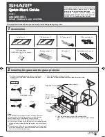
Page 9: ...8 x 20 mm black x 2 Installation bolts 2 M8 x 40 mm black x 2 Operating instructions this document x 1 Light blocking shield x 1 Attaching the Light blocking Shield This part prevents reflection of the cables connected to the back of the Plasma Display on the base cover Note Attach it after anchoring the base cover on a flat stable place Attachment Procedure 1 Remove the double sided adhesive tape...

Page 10: ...e front surface of the base cover may be scratched Base cover Screws 4 mm x 10 mm Stand pipe Screws 4 mm x 10 mm Stand pipe Assembly Procedure Attaching the Light blocking Shield 2 While firmly holding the ends of the light blocking shield apply it with the double sided adhesive tape Note Be careful that the light blocking shield does not catch on the pipe insertion holes Anchor it in place so tha...

Page 11: ...olt when the threads are no longer visible Installation bolt 1 M8 x 20 mm black Sheet Holes a holes in center of Plasma Display Note When laying down the Plasma Display be careful so as to not scratch or damage it 7 Regarding the stand pipe screw holes when the stand is used as a desktop stand Please use A and A in the following diagram A A A A 2 As shown in the above diagram hook the stand pipe h...

Page 12: ...screws hooks chains and other fittings that you use to secure the Plasma Display to prevent it from overturning will vary according to the composition and thickness of the surface to which it will be attached Select the appropriate screws hooks chains and other fittings after first inspecting the surface carefully to determine its thickness and composition and after consulting a professional insta...

Page 13: ...ished by Pioneer Corporation Copyright 2006 Pioneer Corporation All rights reserved 576 22 11 16 1282 50 1 2 149 4 5 7 8 750 5 29 9 16 65 2 9 16 491 19 5 16 335 13 3 16 25 1 62 5 2 15 32 123 1 4 27 32 815 5 32 1 8 150 5 5 15 16 289 5 11 13 32 Installing the Product on a Rack etc When installing on a rack etc please be sure that the Plasma Display is held by two people Caution When holding the Plas...

Page 14: ...é conçu et ne le modifiez pas ou ne l utilisez pas à des fins autres que celles pour lesquelles il a été conçu Une installation incorrecte est extrêmement dangereuse car elle peut provoquer la chute du support ou tout autre accident Lieu d installation Sélectionnez un emplacement assez solide pour sup porter le poids du support et de l écran Assurez vous de placer le produit à un emplacement stabl...

Page 15: ...ication des pièces fournies Veuillez vous assurer que vous possédez bien toutes les pièces nécessaires avant de procéder au montage et à l installation du support Mise en place de l écran occultant Il empêche que les câbles branchés au dos de l écran à plasma ne se reflètent sur la couverture de table Remarque Installez le une fois que vous avez fixé la couverture de table sur une surface plane et...

Page 16: ...ap vous risqueriez d érafler la surface de la couverture de table Procédure de montage Vis 4 mm x 10 mm Colonne de support Colonne de support Vis 4 mm x 10 mm Couverture de table Drap Mise en place de l écran occultant 2 Tout en tenant fermement les extrémités de l écran occultant mettez le en place à l aide du ruban adhésif double face Remarque Veillez à ce que l écran occultant ne déborde pas su...

Page 17: ...s dès que les filets ne sont plus visibles Boulons d installation 1 M8 x 20 mm noir Fentes a fentes dans le centre de l écran à plasma Remarque Veillez à ne pas érafler l écran plasma ni l endommager lorsque vous le couchez 7 Prise en compte des fentes de la colonne de support lorsque le support est utilisé comme support de bureau Reportez vous au A et A du schéma suivant A A A A Boulons d install...

Page 18: ...as contraire l écran plasma pourrait tomber et provoquer des dégâts Les vis crochets chaînes et autres raccords que vous utilisez pour fixer en place l écran plasma afin de l empêcher de basculer dépendront de la composition et de l épaisseur de la surface sur laquelle vous le fixez Choisissez les vis crochets chaînes et autres raccords appropriés après avoir tout d abord soigneusement inspecter l...

Page 19: ...oduit Schéma de dimensions Unité mm 576 1282 149 4 750 5 65 491 335 25 62 5 123 1 815 5 150 5 289 5 Publication de Pioneer Corporation 2006 Pioneer Corporation Tous droits de reproduction et de traduction réservés Installation du produit sur une étagère etc En cas d installation de l écran sur une étagère etc veillez à ce qu il soit maintenu par deux personnes Lorsque vous tenez l écran à plasma d...

Page 20: ...Sie das Produkt nicht anders als angegeben und nehmen Sie keine Veränderungen am Produkt vor Verwenden Sie den Tischständer nicht für ein anderes Plasmadisplay als für die Modelle für die er vorgesehen ist nehmen Sie keine Veränderungen daran vor und verwenden Sie ihn nicht für andere Zwecke Eine falsche Installation ist sehr gefährlich da sie zum Umfallen der Einheit oder zu einem anderen Unfall ...

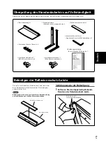
Page 21: ...2 Innensechskantschlüssel Gegenseite 6 mm für M8 Verwendung x 1 Bedienungsanleitung das vorliegende Dokument x 1 Befestigen der Reflexionsschutz Leiste Dieses Teil verhindert die Reflexion der Kabel die an der Basis Abdeckung an die Rückseite des Plasmadisplays angeschlossen sind Hinweis Befestigen Sie die Leiste nachdem Sie die Basisabdeckung an einem flachen und stabilen Ort verankert haben Verf...

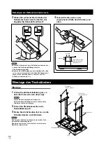
Page 22: ...ratzt wird Montage Basisabdeckung Schrauben 4 mm x 10 mm Ständerelement Schrauben 4 mm x 10 mm Ständerelement Tuch Befestigen der Reflexionsschutz Leiste 2 Kleben Sie während Sie die Enden der Reflexionsschutz Leiste festhalten das doppelseitig klebende Band darauf Hinweis Achten Sie bitte darauf dass die Reflexionsschutz Leiste nicht auf die Einführungs Öffnungen für die Ständerelemente gelangt N...

Page 23: ...gänge der Schrauben nicht mehr sichtbar sind Installationsschrauben 1 M8 x 20 mm schwarz Tuch Schraublöcher a Öffnungen in der Mitte des Plasmadisplays Hinweis Vorsicht beim Hinlegen des Plasmadisplays damit Sie es nicht zerkratzen oder anderweitig beschädigen 7 Die Schraublöcher der Ständerelemente bei Verwendung des Ständers als Plasmadisplay Tischständer Bitte verwenden Sie A und A wie sie in d...

Page 24: ...uben Halteschrauben Ketten und Haken die Sie zur Sicherung des Plasmadisplays verwenden um es vor dem Umfallen zu bewahren können je nach dem Aufbau und der Dicke der Fläche auf der es montiert wird variieren Wählen Sie die jeweils geeigneten Schrauben Halteschrauben Ketten und Haken nachdem Sie sich zunächst die vorgesehene Fläche genau angesehen haben um ihre Dicke und ihren Aufbau zu beurteilen...

Page 25: ...entlicht von Pioneer Corporation Urheberrechtlich geschützt 2006 Pioneer Corporation Alle Rechte vorbehalten 576 1282 149 4 750 5 65 491 335 25 62 5 123 1 815 5 150 5 289 5 Installation des Plasmadisplays an einem Gestell usw Bitte achten Sie darauf dass das Plasmadisplay bei der Installation an einem Gestell usw von zwei Personen gehalten wird Halten des Plasmadisplays in aufrechter Stellung Halt...

Page 26: ...e Montate il supporto secondo le istruzioni di montaggio e fissate bene tutte le viti nelle posizioni predisposte Dopo l installazione del display si possono verificare incidenti imprevisti come la rottura o la caduta dell apparecchio se il supporto non è stato installato secondo le istruzioni Per garantire un installazione sicura il display deve essere montato sempre da due o più persone Prima de...

Page 27: ...i installazione 1 x 2 M8 x 20 mm neri Istruzioni per l uso x 1 questo manuale Bulloni di installazione 2 x 2 M8 x 40 mm neri Fissaggio della protezione antiriflesso Questo pezzo impedisce la riflessione dei cavi collegati alla parte posteriore del display a plasma sul coperchio della base Nota Fissatela dopo aver ancorato il coperchio della base su una superficie piana e stabile Procedura di fissa...

Page 28: ...gio la superficie anteriore del coperchio della base potrebbe graffiarsi Procedura di montaggio Coperchio della base Viti 4 mm x 10 mm Gamba del supporto Viti 4 mm x 10 mm Gamba del supporto Lenzuolo Fissaggio della protezione antiriflesso 2 Tenendo ben ferme le estremità fissate la protezione antiriflesso con il nastro biadesivo Nota Assicuratevi che la protezione antiriflesso non copra i fori di...

Page 29: ...i installazione 1 M8 x 20 mm neri Fori a fori al centro del display a plasma Nota Quando appoggiate il Display a Plasma fate attenzione a non graffiarlo o danneggiarlo 7 Si riferisce ai fori per le viti della gamba del supporto se il supporto viene usato come scrivania Usate A e A come mostrato nello schema qui sotto A A A A 2 Come mostrato nell immagine sopra agganciate i fori delle gambe del sup...

Page 30: ...stro Nota Usate ganci corde e accessori che si trovano sul mercato Gancio consigliato Diametro nominale M8 Lunghezza da 12 mm a 15 mm Per sostenere il display a plasma si dovrebbe usare sempre un tavolo o una superficie del pavimento con resistenza adeguata Se ciò non fosse possibile ne potrebbero derivare danni alle cose o alle persone Durante l installazione del display a plasma prendere le nece...

Page 31: ...a plasma Per montare il display a plasma su una mensola ecc assicuratevi che sia sollevato da due persone Attenzione Dati tecnici Misure esterne 576 mm L x 491 mm A x 335 mm P Peso 5 9 kg Le specifiche sopramenzionate e l aspetto esteriore possono essere modificati senza alcun preavviso per migliorare il prodotto Unità mm Grafico delle misure Pubblicato da Pioneer Corporation Copyright 2006 Pionee...

Page 32: ... mag het voor andere doeleinden worden gebruikt Onjuiste installatie is uiterst gevaarlijk omdat het apparaat daardoor kan vallen of omdat ongelukken kunnen worden veroorzaakt Plaats van installatie Kies een plaats die sterk genoeg is om het gewicht van de staander en de displays te kunnen dragen Zorg ervoor dat de plaats van installatie vlak en stabiel is Plaats het apparaat niet buiten bij een w...

Page 33: ...Montagebouten 1 M8 x 20 mm zwart x 2 Gebruiksaanwijzing deze handleiding x 1 Montagebouten 2 M8 x 40 mm zwart x 2 Bevestiging van de lichtafschermkap Dit element zorgt ervoor dat de kabels die aan de achterzijde van de plasma display op het voetstuk zijn bevestigd geen licht weerkaatsen Let op Bevestig dit element nadat het voetstuk op een vlakke en stabiele ondergrond is vastgezet Wijze van beves...

Page 34: ...de van het voetstuk krassen ontstaan Wijze van montage Bevestiging van de lichtafschermkap 2 Houd de uiteinden van de lichtafschermkap stevig vast en breng de kap met de dubbelzijdige hechtband op het voetstuk aan Let op Zorg ervoor dat de lichtafschermkap niet de invoeggaten voor het opzetstuk afdekt Bevestig de kap stevig op zijn plaats zodat er geen tussenruimte ontstaat Zie figuur rechts Indie...

Page 35: ...der Montagebouten 2 M8 x 40 mm zwart Stap 3 Schuif de staander in de plasma display Stap 2 Tafelbladstaander Let op Bevestig de plasma display zodanig dat de lichtafschermkap de onderzijde van het achteroppervlak van de display raakt Zie blz 37 voor plaatsing op een rek etc Het gewicht van de plasma display bedraagt ongeveer 40 kg vanwege hun vlakke vorm zijn ze instabiel Vanwege hun vlakke vorm z...

Page 36: ...roefhaak Nominale diameter M8 Lengte 12 mm tot 15 mm De tafel of het gedeelte van de grond dat voor de apparatuur wordt gebruikt dient stevig genoeg te zijn ter ondersteuning van de plasma display indien dit niet het geval is kan lichamelijk letsel worden veroorzaakt Zorg ervoor wanneer de plasma display wordt geïnstalleerd dat de juiste maatregelen worden getroffen zodat deze niet valt of kantelt...

Page 37: ...e plasma display door twee personen wordt vastgehouden wanneer deze op een rek etc wordt geplaatst Waarschuwing Eenheid mm Afmetingen Uitgegeven door Pioneer Corporation Copyright 2006 Pioneer Corporation Alle rechten voorbehouden Technische gegevens Afmetingen buitenzijde 576 mm B x 491 mm H x 335 mm D Gewicht 5 9 kg Het is mogelijk dat bovenstaande gegevens en de buitenzijde zonder voorafgaande ...

Page 38: ...utilice este soporte para una pantalla de plasma distinta de las indicadas ni lo modifique ni lo destine a otros usos Si la instalación no se efectúa correctamente las consecuencias podrían ser extremadamente peligrosas incluyendo la caída de la pantalla u otros accidentes imprevistos Dónde instalar el soporte Elija un lugar cuya resistencia permita aguantar el peso del soporte y de la pantalla As...

Page 39: ...x 20 mm negros x 2 Manual de instrucciones este documento x 1 Tornillos de fijación 2 M8 x 40 mm negros x 2 Cómo instalar el dispositivo antirreflejos Esta pieza impide que los cables conectados en la parte posterior de la pantalla de plasma se reflejen en la base de apoyo Nota Instale el dispositivo tras haber dispuesto firmemente la base de apoyo sobre una superficie llana y estable Procedimient...

Page 40: ...e de apoyo se podría rayar Procedimiento de montaje Cómo instalar el dispositivo antirreflejos 2 Sujete firmemente los extremos del dispositivo antirreflejos y péguelo mediante la cinta adhesiva de doble cara Nota Tenga cuidado de que el dispositivo antirreflejos no interfiera con los agujeros de tornillos de las columnas Colóquelo de manera que no quede ningún hueco ya que en tal caso el disposit...

Page 41: ...izar la instalación sobre un bastidor u otra estructura similar consulte la pág 43 Una pantalla de plasma pesa alrededor de 40 kg Puesto que carecen de fondo son inestables Por consiguiente es imprescindible que al menos dos personas intervengan en su montaje e instalación Nota Introduzca verticalmente los tornillos en los agujeros Extienda una sábana o cubierta protectora para evitar que la panta...

Page 42: ...Para apoyar la pantalla de plasma siempre debe utilizarse una mesa o un área del piso con la resistencia adecuada De no ser así se podrían causar lesiones personales y daños físicos Al instalar la pantalla de plasma adopte las medidas de seguridad necesarias para evitar que la misma se caiga o se vuelque en caso de emergencias como terremotos o de accidentes Si no adopta estas precauciones la pant...

Page 43: ...ration Copyright 2006 Pioneer Corporation Todos los derechos reservados Especificaciones Dimensiones externas 576 mm ancho x 491 mm alto x 335 mm fondo Peso 5 9 kg Las anteriores especificaciones y el exterior podrán modificarse sin previo aviso con objeto de mejorar el producto Cómo instalar el producto sobre un bastidor u otra estructura similar Cuando instale este producto en un bastidor u otra...

Page 44: ...所設計 的 如果使用其他機種 可能會因為不穩定而造成傷害 想 要獲得更進一步的資訊 請跟你購買顯示器的店家聯絡 除了詳細的指示 請不要安裝或修改產品 除了那些指示說 明 請不要將此支架安裝電漿顯示器 也不要修改或是另有 用途 不當的安裝是非常危險的 因為如此可能會造成翻覆或是其他 意外 安裝位置 選擇一個夠堅固 足以支撐桌上支架和顯示器的地方 確認是安裝於平坦和堅固的地方 切勿將本產品安裝於室外 溫泉處或沙灘附近 不要將支架安裝於會震動或衝撞的地方 組合和安裝 請按照裝配指示組合桌上支架 將所有螺絲穩固的栓在指定 的地方 安裝顯示器以後 因為桌上支架沒有按照指示安裝 可能會 發生幾種狀況 如設備碎裂或是翻覆的意外發生 安裝顯示器時一定要有兩人或兩人以上去確認是否安裝妥當 安裝以前 將顯示器和周邊設備的電源關閉 然後再將電源 線插頭從插座拔除 防止產品的翻覆造成的意外 如地震等等 請確實的量...

Page 45: ...標準配件 再行組裝及安裝 接合遮光罩 座板 1 支架管 左右各一隻 可互換 2 六角扳手 1 另一端6 mm為M8專用 螺絲 4 mm 10 mm 4 安裝螺栓 1 M8 x 20 mm 黑色 2 安裝螺栓 2 M8 x 40 mm 黑色 2 操作手冊 本份文件 1 遮光罩 1 此部分可預防連接至電漿顯示器背面連接線之反射光到底蓋 上 附註 將座板固定到一平坦 穩定之處後 再將其接上 接合程序 1 撕去遮光罩上的雙面膠帶 撕去每條雙面膠帶 遮光罩 座板 ...

Page 46: ...將它接上 附註 小心遮光罩不要扣到支架管安插孔上 固定於定位時不要有任何空隙 如右圖 如有空隙 遮光罩可能會剝落 3 從上往下壓 並固定於定位 組裝支架 組裝程序 1 將座板翻轉使底面朝上 附註 在翻轉座板時 小心不要刮傷遮光罩 2 將支架管插入座板內 3 上緊螺栓以穩定支架管 附註 組裝支架管時 請於座板放置一軟墊 組裝前若未放置軟墊 則座板正面可能會刮傷 螺絲 4 mm 10 mm 支架管 座板 軟墊 壓 壓 確定沒有空隙 螺絲 4 mm 10 mm 支架管 ...

Page 47: ...側面看不見螺紋為止 螺栓如果完全鎖入 將無法接上顯示器 電漿顯示器 看不見螺紋時 停止 向下鎖入螺栓 安裝螺栓1 M8 20 mm 黑色 a 固定孔 位於電漿顯示器 中間的固定孔 軟墊 安裝螺栓1 電漿顯示器機體 附註 在放下電漿顯示器時 小心不要有所刮傷 將支架用作桌架時 請注意支架管上的螺絲孔 請利用下圖中的 A及 A 孔 A A A A 2 如上圖所示 將支架管固定孔 A 扣到安裝螺栓 1的螺絲頭上 然後將支架向上滑入主顯示器 直到與安裝螺栓 1接合為止 3 將安裝螺栓 2 M8 40 mm 黑色 穿孔支 架管孔 A 然後利用六角扳手將它們鎖入主電 漿顯示器內 請確實將螺栓上緊 4 利用六角扳手確實上緊安裝螺栓 1 請確實將螺栓上緊 安裝螺栓2 M8 40 mm 黑色 步驟3 桌上支架 遮光罩 桌上支架 電漿顯示器 滑動支架 步驟2 附註 接上電漿顯示器 使遮光罩能觸及其背面下方 要...

Page 48: ...20 mm長的螺絲 螺絲的位置 要將支架穩固於桌上時 請使用額定直徑為6 mm及至少 20 mm長的螺絲 單位 mm 301 29 120 581 11 側面 1 掛鉤 2 鋼索 固定配件 要有足夠強度的桌上或是地上才可永久支撐電漿顯示 器 如果強度不夠將可能導致個人傷害和身體的損害 當安裝電漿顯示器時 請先量測安全的尺度 如果發生 緊急狀況 比如地震或是意外 可以避免機台翻覆或是 翻倒 如果你沒有做這預防措施 那麼電漿顯示器有可能會翻覆 且造成傷害 使用螺絲 掛鉤 鏈條 和其他裝配來穩固電漿顯示器 以防翻倒會因為嵌入合成的材質或是表面厚度的不同而 有所差別 當有必要時再詢問專業安裝員以後 首先小心審查嵌入 表面的厚度和材質 並選擇適當的螺絲 掛鉤 鏈條 和其他裝配 注意 在安裝支架後 請特別小心確定設備不會摔落 9 mm 至 15 mm 最少20 mm 6 mm M8 12 mm 至 1...

Page 49: ...機架等裝置上 在安裝到機架等裝置上時 請務必由兩人合力握住 在放下電漿顯示器時 如何垂直握住電漿顯 示器 如何握住電漿顯示器 576 1282 149 4 750 5 65 491 335 25 62 5 123 1 815 5 150 5 289 5 規格 外部尺寸 576 mm 寬 491 mm 高 335 mm 深 重量 5 9公斤 以上的外部規格如有修改 以改善產品品質 恕不另行通知 日本先鋒公司出版 版權 2006日本先鋒公司 版權所有 注意 ...

Page 50: ...555 PIONEER ELECTRONICS AUSTRALIA PTY LTD 178 184 Boundary Road Braeside Victoria 3195 Australia TEL 03 9586 6300 PIONEER ELECTRONICS DE MEXICO S A DE C V Blvd Manuel Avila Camacho 138 10 piso Col Lomas de Chapultepec Mexico D F 11000 TEL 55 9178 4270 153 8654 東京都目黒区目黒1丁目4番1号 Printed in Japan Imprimé au Japon AZR1176 A Published by Pioneer Corporation Copyright 2006 Pioneer Corporation All rights ...

Reviews: