PDP-425CMX
69
5
6
7
8
5
6
7
8
C
D
F
A
B
E
6. ADJUSTMENT
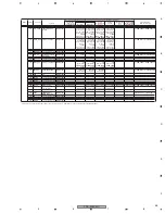
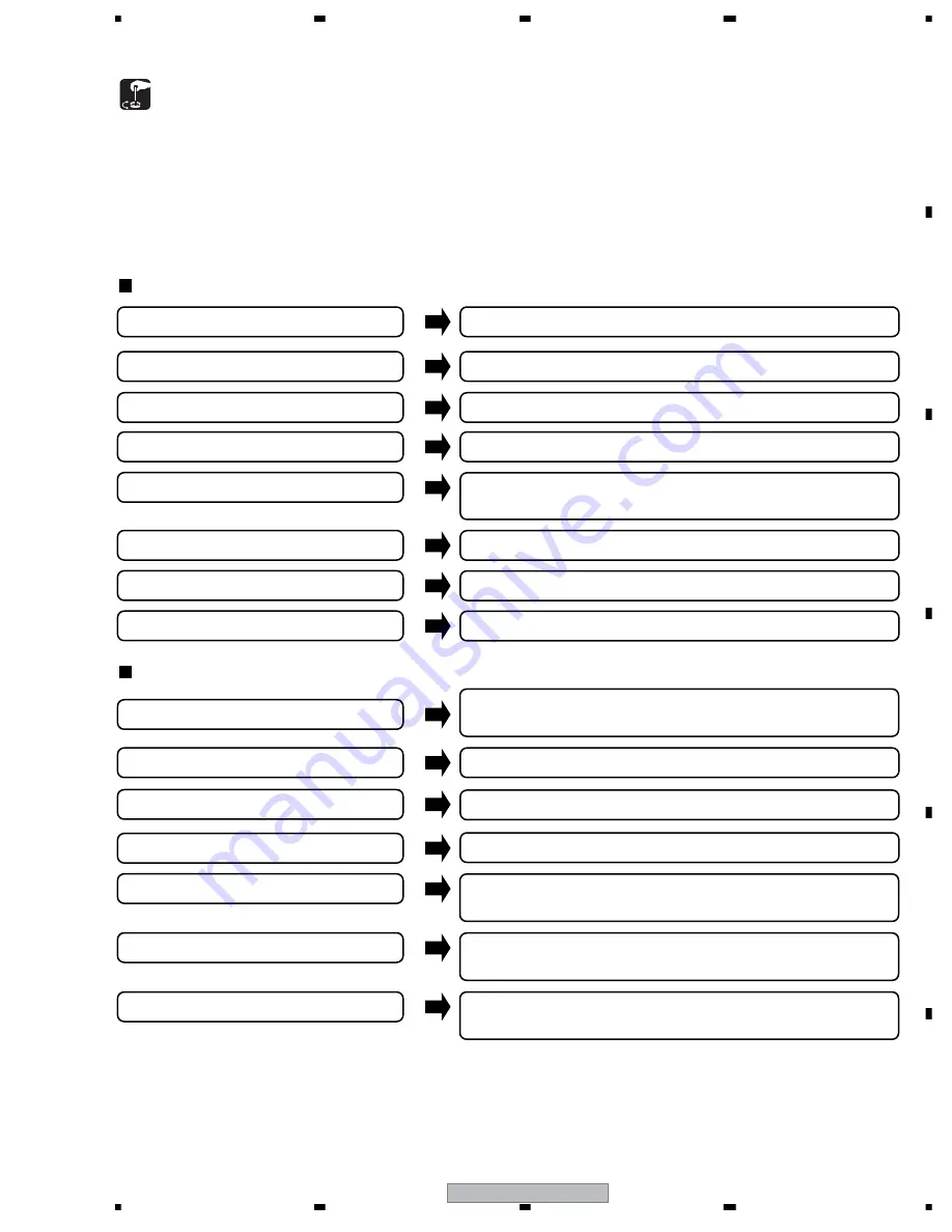
6.1 ADJUSTMENT REQUIRED WHEN THE SET IS REPAIRED OR REPLACED
1. At shipment, the unit is adjusted to its best conditions. Normally, it is not necessary to readjust even if an assembly is replaced. If the
adjustment is shifted or if it becomes necessary to readjust because of part replacement, etc., perform the adjustment as described below.
2. Any value changed in Service/Factory mode will be stored in memory as soon as it is changed. Before readjustment, take note of the
original values for reference in case you need to restore the original settings.
3. Use a stable AC power supply.
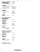
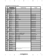
42 Y DRIVE Assy
No adjustment required
POWER SUPPLY Unit
No adjustment required
MD DIGITAL Assy
42 X DRIVE Assy
No adjustment required
Refer to the "7.1.5 BACKUP WHEN THE MAIN UNIT IS ADJUSTED"
MAIN Assy
Refer to the "ADJUSTMENT"
SUB Assy (Audio, 232C, Sensor, etc.)
No adjustment required
MAIN Assy
SUB Assy (Audio, 232C, Sensor, etc.)
Other assemblies
No adjustment required
Service Panel
Refer to the "6.7 METHOD FOR REPLACING THE SERVICE
PANEL ASSY."
POWER SUPPLY Unit
MD DIGITAL Assy
No adjustment required
No adjustment required
No adjustment required
42 X DRIVE Assy (IC1101, IC1102)
42 Y DRIVE Assy (IC2201, IC2202)
Other assemblies
When any of the following assemblies is replaced
When any part in the following assemblies is replaced
The assembly must be replaced as a unit, and no part
replacement is allowed.
The assembly must be replaced as a unit, and no part
replacement is allowed except the part of note 1.
The assembly must be replaced as a unit, and no part
replacement is allowed except the part of note 2.
The assembly must be replaced as a unit, and no part
replacement is allowed.
Note 1: MAIN Assy
IC500, IC5002, IC5004, IC5005, IC5007, IC5008, IC5301, IC5304, IC5305, IC5307,
IC5603–IC5606, IC5902 , IC5903, IC5904, IC9504, IC6301, IC6302, IC6304,
IC8002, IC8003, IC8501, X8001, X8002, X9501
Note 2: SUB Assy
IC3001,IC3002,IC3004,
IC2301,U2401,Q2301,Q2302
Summary of Contents for PDP-42MXE10
Page 9: ...PDP 425CMX 9 5 6 7 8 5 6 7 8 C D F A B E ...
Page 27: ...PDP 425CMX 27 5 6 7 8 5 6 7 8 C D F A B E ...
Page 37: ...PDP 425CMX 37 5 6 7 8 5 6 7 8 C D F A B E ...
Page 129: ...PDP 425CMX 129 5 6 7 8 5 6 7 8 C D F A B E ...
Page 132: ...PDP 425CMX 132 1 2 3 4 1 2 3 4 C D F A B E MAIN PWB CONNECTOR WAVE FORM POINT SIDE B ...

