PDP-425CMX
164
1
2
3
4
1
2
3
4
C
D
F
A
B
E
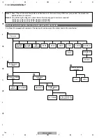
7.1.9 DISASSEMBLY
It is efficient to proceed with removal of the main parts and boards in the order shown in the chart below:
Chart of removal order for the main parts and boards
Front case Assy
(425CMX)
1
Bottom cover
(CMX)
3
4
4
5
2
Rear case
Front chassis LA
Front chassis L (FT)
AC bracket (CMX)
Assy
COMM bracket
(CMX)
POWER
SUPPLY
Multi base
(CMX)
SUS
CLAMP 1
SUS
CLAMP 2
MAIN
VSIF
AUDIO
SENB
SENC
SEND
KEY
LED2
COMMSLOT
COMMSLOT
IF
SCAN IC
42 X DRIVE
MD DIGITAL
42 Y DRIVE
Fan motor
80
×
25L
Note 1:
Even if the unit shown in the photos and illustrations in this manual may differ from your product, the procedures
described here are common.
Note 2:
For performing the diagnosis shown below, the following jigs for service is required:
• Extension cable for 42 inch PDP diagnosis (GGD1469)
• Extension cable for 42 inch PDP diagnosis (GGP1075)
Summary of Contents for PDP-42MXE10
Page 9: ...PDP 425CMX 9 5 6 7 8 5 6 7 8 C D F A B E ...
Page 27: ...PDP 425CMX 27 5 6 7 8 5 6 7 8 C D F A B E ...
Page 37: ...PDP 425CMX 37 5 6 7 8 5 6 7 8 C D F A B E ...
Page 129: ...PDP 425CMX 129 5 6 7 8 5 6 7 8 C D F A B E ...
Page 132: ...PDP 425CMX 132 1 2 3 4 1 2 3 4 C D F A B E MAIN PWB CONNECTOR WAVE FORM POINT SIDE B ...

