125
PDP-433CMX
5
6
7
8
5
6
7
8
C
D
F
A
B
E
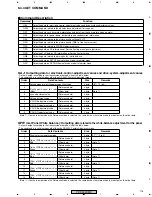
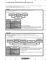
• Operations : When a microcomputer detected abnormality, it turns the power supply OFF.
• LED display : Blinking in green
How to release shutdown
If the Power key on the remote control unit is pressed, the shutdown
status is released, and the unit will be turned on. (It is not necessary
to press the MAIN POWER button to turn off the unit.)
Example: How the LED blinks when DIGITAL-IIC communications fail
• Operations : In an emergency, the protection circuits are activated, and the power is turned off.
• LED display : Blinking in red
Note: If more than two protection circuits are activated at almost the same time, the LED indicates this by its
blinking-pattern.
Example: How the LED blinks for the first power-down (Y-DC/DC CONVERTER) and the second power-down (Y DRIVE)
Number of
blinks
Failure Point
1
Y-DRIVE
2
Y-DC/DC CONVERTER
3
X-DC/DC CONVERTER
4
X-DRIVE
5
Power supply
6
Address junction
7
Address resonance
8
DIGITAL-DC/DC CONVERTER
Shutdown
Power-down
Green LED lights
for 200 msec.
Extinguished
for 3 sec
Green LED lights
for 200 msec.
Extinguished
for 100 msec
This unit has self-diagnosis functions against abnormalities in the internal circuits and other operational abnormalities, and if any abnormality is
detected, the STANDBY/ON indicator (LED) blinks to alert you of it.
How the indicator blinks and possible failure points and power-down points are explained below:
1st power-down information
2nd power-down
information
Red LED lights
for 200 msec.
Extinguished
for 3 sec
Extinguished
for 1 sec
Red LED lights
for 200 msec.
Extinguished
for 100 msec
Red LED lights
for 200 msec.
How to release power-down
Set the MAIN POWER button to OFF, and wait for about 30 seconds until
the LED for PD (power-down) in the power-supply module is extinguished.
Wait another 5 seconds, then recover the unit by setting the MAIN
POWER button to ON.
Note:
After power-down is released, the unit restarts and goes to Standby
mode.
Number of
blinking
Reason
1
Panel Microcomputer failure
2
DIGITAL-IIC communication failure
3
Condensation
4
Temperature abnormality
5
FAN abnormality
6
Module microcomputer failure
7
Wide microcomputer failure
8
RGB-IIC communication failure
9
Audio failure
7.1.2 DIAGNOSIS FOR SHUTDOWN AND POWER-DOWN BY LED
Summary of Contents for PDP 433CMX
Page 165: ...165 PDP 433CMX Pin Assignment Top View CXA3516R RGB ASSY IC4603 AD PLL IC ...
Page 166: ...166 PDP 433CMX Block Diagram ...
Page 167: ...167 PDP 433CMX Pin Function ...
Page 168: ...168 PDP 433CMX ...
Page 169: ...169 PDP 433CMX ...

