70
PDP-433CMX
1
2
3
4
C
D
F
A
B
E
1
2
3
4
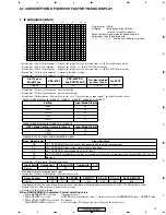
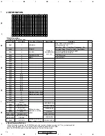
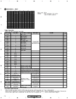
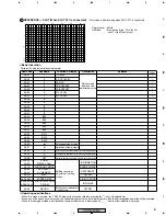
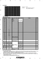
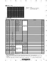
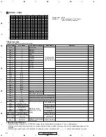
Notes on Operation with the Remote Control Unit
• In this manual, keys that are not on the remote control unit (AXD1459) supplied with the Plasma Display are designated as direct-select
keys.
• To select items in Service Factory mode with the AXD1459, press the following keys as many times as required:
For selection of main items: MUTE key
For selection of other items:
5
(UP) or
∞
(DOWN) key
Change of Settings When Entering Service Factory Mode
1
Settings of MENU mode
• The settings for PICTURE items are reset to the center values.
Note: The PICTURE adjustment values to be reset are limited to the following:
For VIDEO: Those for the current signal mode of the selected input function
For a PC: Tables A-H are reset according to the history of the input signal mode
• All settings for SCREEN items are reset to the center values.
Note: The SCREEN adjustment values to be reset are only those for the current signal mode of the selected input function.
This is because the adjustment values of the MENU mode can be reset to the center values by executing FINAL SETUP or
PICTUREDEFAULT.
• The settings for SETUP and OPTION of the MENU mode are maintained, except for the following:
COLOR TEMP: It is reset to MIDDLE.
AUTO POWER OFF/POWER MANAGEMENT: The settings are maintained, but these functions do not work.
2
Adjustment values of the Integrator mode
• The following adjustment values for PICTURE and WHITE BAL are reset to the default values:
Note: The PICTURE and WHITE BAL adjustment values to be reset are limited to the following:
For VIDEO: Those for the current signal mode of the selected input function
For a PC: Tables A-H are reset according to the history of the input signal mode.
• The SCREEN settings are maintained.
• The settings for SETUP and OPTION of the Integrator menu are maintained, except for the following:
SIDE MASK LEVEL: The adjustment values are reset to the default values.
FULL MASK that has been set in Integrator mode: Released
OFF TIMER: Released
• The COLOR MODE (Integrator menu) settings that have been set in the Integrator menu are maintained.
3
Others
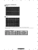
• If the input signal mode is changed in Service Factory mode, settings are changed according to the input signal mode, Service Factory
mode is maintained, and its default display (INFORMATION VERSION) appears.
Note: When the input signal mode is changed, settings are reset as shown in
1
and
2
above.
• If FUNCTION switching is executed in Service Factory mode, the function is switched to the selected one, Service Factory mode is
maintained, and its default display (INFORMATION VERSION) appears.
Note: When the FUNCTION is changed, settings are reset as shown in
1
and
2
above.
• The COLOR DETECT setting is performed based on the COLOR SYSTEM selected in MENU mode.
• Only the data at addresses 0100 to 01FF of the module microcomputer/EEPROM are copied (updated) to the module microcomputer area
of the main microcomputer EEPROM.
• Various panel protection functions (still-picture detection, block-brightness detection, SCAN IC protection function) are deactivated.
Note: The protection functions are kept deactivated even after you exit Service Factory mode. To reactivate these functions, after exiting
Service Factory mode, be sure to turn the power off, then back on.
• While there is no input, The partial setting, or while incompatible PC signals are input, settings that are not dependent on the
signal mode can be performed. (For the MASK setting, see "MASK 1," and "MASK 2.") The setting items that are dependent on the
input signal mode are grayed on the display and cannot be changed.
Summary of Contents for PDP 433CMX
Page 165: ...165 PDP 433CMX Pin Assignment Top View CXA3516R RGB ASSY IC4603 AD PLL IC ...
Page 166: ...166 PDP 433CMX Block Diagram ...
Page 167: ...167 PDP 433CMX Pin Function ...
Page 168: ...168 PDP 433CMX ...
Page 169: ...169 PDP 433CMX ...


