PDP-5010FD
105
5
6
7
8
5
6
7
8
C
D
F
A
B
E
A
.
P
N E L
L
/
1
[
B
T
6 0 V S ]
F A C T
A
R
S T E R
M A S K
S E T U P
)
( +
A
.
P
N E L
L
/
1
[
B
T
6 0 V S ]
F A C T
S
R
T
M A S K
0 1
0
: 6
V
V
–
D 1
1
5
0 6 0
– N T V
T
A
–
B
V
–
D 1
1
5
0 6 0
– N T V
T
A
–
B
1
5
10
15
16
1
5
10
15
20
25
30
32
1
5
10
15
16
1
5
10
15
20
25
30
32
1
2
3
4
5
6
7
8
9
A
B
C
D
E
1
2
3
4
5
6
7
8
9
A
B
C
D
E
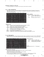
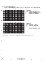
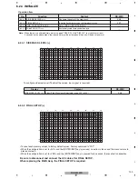
6.2.2.9 RASTER MASK SETUP (+)
• This menu set the RASTER MASK and the drive sequence at RASTER MASK state. Pressing the ENTER/SET key
shifts the screen to the next nested layer below for item selection.
<DOWN> : Shifting to PATTERN MASK SETUP
(+)
<UP>
: Shifting to ETC. (+)
<SET>
: Shifting to the next nested layer
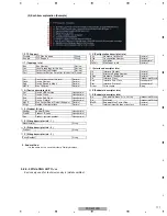
• The MASK indication sequence can be changed among 48V, 50V, 60V, 72V, 75V and 60P using the Right or
Left key. The selected sequence and the ABL/WB table are retained until the mask is turned off.
<DOWN> : Shifting to the next MASK
<UP>
: Shifting to the previous MASK
<RIGHT> : Changing MASK sequence (+)
<LEFT>
: Changing MASK sequence (-)
<SET>
: Determining the adjustment/setting
value and shifting to the upper layer
g
Key operation
g
Key operation
A
R
S T E R
M A S K
S E T U P
Summary of Contents for PDP-5010FD
Page 19: ...PDP 5010FD 19 5 6 7 8 5 6 7 8 C D F A B E ...
Page 20: ...PDP 5010FD 20 1 2 3 4 1 2 3 4 C D F A B E 4 BLOCK DIAGRAM 4 1 OVERALL WIRING DIAGRAM 1 2 ...
Page 23: ...PDP 5010FD 23 5 6 7 8 5 6 7 8 C D F A B E ...
Page 35: ...PDP 5010FD 35 5 6 7 8 5 6 7 8 C D F A B E ...
Page 167: ...PDP 5010FD 167 5 6 7 8 5 6 7 8 C D F A B E ...
Page 178: ...PDP 5010FD 178 1 2 3 4 1 2 3 4 C D F A B E 10 6 PANEL CHASSIS SECTION ...

