PDP-5010FD
54
1
2
3
4
1
2
3
4
C
D
F
A
B
E
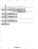
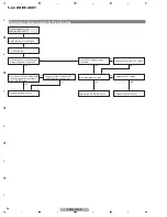
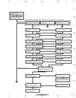
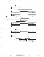
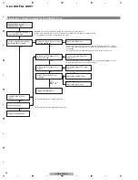
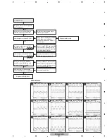
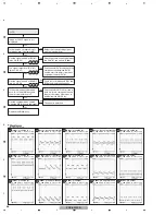
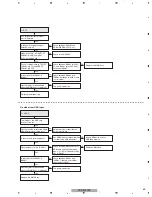
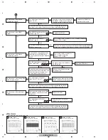
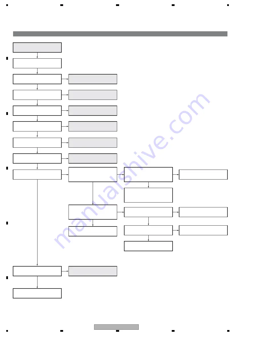
5.2.6 VIDEO SYSTEM
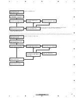
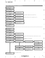
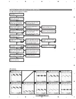
Flowchart of Failure Analysis for The Video System
Is the selected input signal a
terrestrial analog TV?
Are the data displayed on the
"HDMI SIGNAL INFO" page of
the Factory menu correct?
The source equipment previously
used is in failure.
No problem with the MAIN Assy.
Is the sync signal output from
IC5201?
Does the result of SIG mode
detection on the Factory menu
coincide with the input signal data?
Yes
No
No
No
OK
After changing the source
equipment, check the "HDMI
SIGNAL INFO" data again.
NG
Replace the MAIN Assy.
No
Replace the MAIN Assy.
The input signal is not displayed.
=> TV
Is the selected input signal a
composite signal?
Yes
No
=> COMP / S
=> PC
Is the selected input signal a
component signal?
Yes
=> COMP / PC1
Is the selected input signal a
S-video signal?
Is the selected input signal an
PC signal?
Yes
No
Is the selected input signal an
HDMI signal?
Yes
Yes
=> DTV
Is the selected input signal a
digital TV signal?
Yes
=> USB_E / USB_R
Is the selected input signal a
USB signal?
No problem with the MAIN Assy
Yes
No
No
Yes
Yes
Yes
Is the sync signal input to IC8001?
No
Replace the MAIN Assy.
Replace the MAIN Assy.
Yes
Replace the MAIN Assy.
No
No
No
=> COMP / S
Failure analysis for the
MAIN Assy => MA3
Summary of Contents for PDP-5010FD
Page 19: ...PDP 5010FD 19 5 6 7 8 5 6 7 8 C D F A B E ...
Page 20: ...PDP 5010FD 20 1 2 3 4 1 2 3 4 C D F A B E 4 BLOCK DIAGRAM 4 1 OVERALL WIRING DIAGRAM 1 2 ...
Page 23: ...PDP 5010FD 23 5 6 7 8 5 6 7 8 C D F A B E ...
Page 35: ...PDP 5010FD 35 5 6 7 8 5 6 7 8 C D F A B E ...
Page 167: ...PDP 5010FD 167 5 6 7 8 5 6 7 8 C D F A B E ...
Page 178: ...PDP 5010FD 178 1 2 3 4 1 2 3 4 C D F A B E 10 6 PANEL CHASSIS SECTION ...

