background image


 PDP-5016

Model:

SERVICE MANUAL

Safety Precaution
Technical Specifications
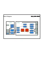
Block Diagram
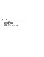
Circuit Diagram
Basic Operations & Circuit Description
Main IC Specifications
Trouble Shooting Manual of PDP Module
Spare Part list 
Exploded View
If You Forget Your V-CHIP Password 
Software Upgrade

This manual is the latest at the time of printing, and does not
include the modification which may be made after the printing,
by the constant improvement of product.

Summary of Contents for PDP-5016

Page 1: ...rcuit Description Main IC Specifications Trouble Shooting Manual of PDP Module Spare Part list Exploded View If You Forget Your V CHIP Password Software Upgrade This manual is the latest at the time of printing and does not include the modification which may be made after the printing by the constant improvement of product ...

Page 2: ...sk of electric shock to persons The exclamation point within an equilateral triangle is intended to alert the user to the presence of important operating and maintenance servicing instructions in the literature accompanying the appliance CAUTION TO REDUCE THE RISK OF ELECTRIC SHOCK DO NOT REMOVE COVER OR BACK NO USER SERVICEABLE PARTS INSIDE REFER SERVICING TO QUALIFIED SERVICE PERSONNEL ONLY CAUT...

Page 3: ...away from high voltage or high tempera ture components 8 Before returning the set to the customer always perform an AC leakage current check on the exposed metallic parts of the cabinet such as antennas terminals screwheads metal overlay control shafts etc to be sure the set is safe to operate without danger of electrical shock Plug the AC line cord directly to the AC outlet do not use a line isol...

Page 4: ...BER OF PAGES 9 REVISIONS ISSUED DATE DESCRIPTION RAISED BY SPECIFICATION AGREED SIGNATURE DATE R D DEPARTMENT COMMERCIAL DEPARTMENT PRODUCTION DEPARTMENT Q A DEPARTMENT CUSTOMER SPECIFICATION APPROVED SIGNATURE DATE NOTE Only documents stamped Controlled Document to be used for manufacture of production parts ...

Page 5: ...00 photometer 1 6 Magnetic field no restricted 1 7 Control settings Brightness Contrast Tint Color set at Center 50 1 8 Power input 100 240Vac 1 9 Ambient temperature 20 C 5 C 68 F 9 F 1 10 Display mode 31 5KHz 60Hz Resolution 1366 x 768 1 11 Other conditions 1 11 1 With image sticking protection of PDP module the luminance will descend by time on a same still screen and rapidly go down in 5 minut...

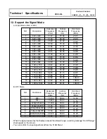
Page 6: ...dc for 1 sec 3 Display 3 1 Screen Size 50 Plasma display 3 2 Aspect Ratio 16 9 3 3 Pixel Resolution 1366x768 3 4 Peak Brightness 1000 cd m Panel module without filter 3 5 Contrast Ratio Dark room 4000 1 Panel module without filter 3 6 Viewing Angle Over 160 3 7 OSD language English 4 Signal 4 1 AV Graphic input 4 1 1 TV standard NTSC PAL N PAL M 4 1 2 TV Tuning system PLL 181CH 4 1 3 CATV 125CH 4 ...

Page 7: ...ransport 5 2 1 Temperature 20 C to 60 C 4º to 140 F 5 2 2 Relative humidity 5 to 95 6 Panel Characteristics 6 1 Type LG50X2 6 2 Size 50 1190mm width x7005mm height x59mm depth 1 mm 6 3 Aspect ratio 16 9 6 4 Viewing angle Over 160 6 5 Resolution 1366X768 6 6 Weight 22 0kg 0 5 kg Net 6 7 Color 1024 R X1024 G X1024 B COLORS 6 8 Contrast Average 60 1 In a bright room with 150Lux at center Typical 4000...

Page 8: ...gnals source 7 2 Stand by Button Switch on main power or switch off to enter power Saving modes 7 3 Main Power Switch Turn on or off the unit 8 OSD Function 8 1 Picture State Normal Dark Bright User Display Bright contrast Color Hue Temp warm Cool Normal User Position H posit V posit Phase H size Auto Adjust 8 2 Sound Setup Mode AVC Volume Balance Equalizer 120HZ 500HZ 1 5KHZ 5KHZ 10KHZ BBE Setup ...

Page 9: ...GES 9 Agency Approvals Safety UL60950 Emissions FCC class B 10 Reliability 11 1 MTBF 20 000 hours Use moving picture signal at 25 C ambient 11 Accessories User manual x1 Remote control x1 Stand x1 Power cord x1 Battery x 2 Accessories box x 1 Speaker x 2 Speaker wire x2 ...

Page 10: ...0 24 31 50 31 50 28 32 36 00 40 00 49 50 50 00 57 27 65 00 75 00 78 75 80 37 94 51 108 03 108 04 108 00 1152 x 864 1152 x 864 1 2 3 5 6 7 8 9 10 11 12 13 14 15 16 17 18 19 4 12 Support the Signal Mode A D Sub Mode VGA or DVI NO 480 i 576 i 720p 1280x720 Resolution 576p 720x576 720p 1280x720 480p 720x480 1080i 1920x1080 1080i 1920x1080 Horizontal Frequency KHz Vertical Frequency Hz Dot Clock Freque...

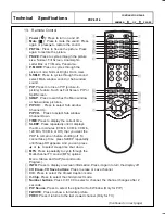
Page 11: ...eatedly until it displays the time in minutes 30 Min 60 Min 90 Min 120 Min 180 Min or Off that you want the PDP to remain on before shutting off To cancel Sleep Time press SLEEP repeatedly until Sleep Off appears And you can press or to select sleep time shut down MTS Press repeatedly to cycle through the Multi channel TV sound MTS options Mono Stereo and SAP Second Audio Program INFO Press to dis...

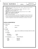
Page 12: ... buttons in the OSD Menu screen and they can be used for the selection of the program when the OSD Menu is not shown on the screen They are used as buttons in the OSD Menu screen and they can be used for the adjustment of volume when the OSD Menu is not shown on the screen CONTINUATION PAGE Technical Specifications PDP 5016 NUMBER 9 OF 9 PAGES PHYSICAL CHARACTERISTICS 14 Power Cord Length 1 8m nom...

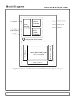
Page 13: ...ommon sustain driver Display data Driver timing Memory Controller Driver Timing Controller Input Interface Controller Vcc 5V Va 55V 65V Vs 180V 190V Control Signal Serial Interface APL Data LVDS Input Applied Voltage level is specified at the time when Full White pattern is displayed on the panel Block Diagram ...

Page 14: ...De Interlacer YCrCb DVI Tuner x 2 SCART1 Sil161B DVI Receiver MSP34x0G Audio Decoder AD9883A ADC VPC3230D Vide Decoder TDA8946 Audio AMP S Video YPbPr Video2 Speaker M52790 A V Switch uPD64083 3D Y C Separator SDA5550 TVText Pro Z86229 V Chip CC VPC3230D Video Decoder Main Board W78E65B System Control Z86229 V Chip CC Sub Board ...

Page 15: ...Circuit Diagram Power supply board of PDP Module USP650M 50LP Main Video board Audio Tuner board Keypad board Remote control receiver board Remote control board ...

Page 16: ......

Page 17: ...DbhM4812V12_Vtek_BOM sch 2 Wed Oct 06 23 58 08 2004 ...

Page 18: ...DbhM4812V12_Vtek_BOM sch 3 Wed Oct 06 23 58 10 2004 ...

Page 19: ...DbhM4812V12_Vtek_BOM sch 4 Wed Oct 06 23 58 11 2004 ...

Page 20: ...DbhM4812V12_Vtek_BOM sch 5 Wed Oct 06 23 58 15 2004 ...

Page 21: ...DbhM4812V12_Vtek_BOM sch 6 Wed Oct 06 23 58 16 2004 ...

Page 22: ...DbhM4812V12_Vtek_BOM sch 7 Wed Oct 06 23 58 18 2004 ...

Page 23: ...DbhM4812V12_Vtek_BOM sch 8 Wed Oct 06 23 58 29 2004 ...

Page 24: ...DbhM4812V12_Vtek_BOM sch 9 Wed Oct 06 23 58 20 2004 ...

Page 25: ...DbhM4812V12_Vtek_BOM sch 10 Wed Oct 06 23 58 22 2004 ...

Page 26: ...DbhM4812V12_Vtek_BOM sch 11 Wed Oct 06 23 58 32 2004 ...

Page 27: ...DbhM4812V12_Vtek_BOM sch 12 Wed Oct 06 23 58 25 2004 ...

Page 28: ...DbhM4812V12_Vtek_BOM sch 13 Wed Oct 06 23 58 27 2004 ...

Page 29: ...Dbh1S4909V12 sch 2 Thu Oct 07 00 30 42 2004 ...

Page 30: ...Dbh1S4909V12 sch 3 Thu Oct 07 00 30 43 2004 ...

Page 31: ...Dbh1S4909V12 sch 4 Thu Oct 07 00 30 45 2004 ...

Page 32: ...Dbh1S4909V12 sch 5 Thu Oct 07 00 30 47 2004 ...

Page 33: ...Dbh1S4909V12 sch 6 Thu Oct 07 00 30 49 2004 ...

Page 34: ...Dbh1S4909V12 sch 7 Thu Oct 07 00 30 50 2004 ...

Page 35: ...Dbh2S4909V12 sch 2 Thu Oct 07 00 32 34 2004 ...

Page 36: ...DUBHE OSD Ver1 1_NAKS sch 1 Mon Oct 18 11 47 11 2004 ...

Page 37: ...0025 sch 1 Mon May 16 09 25 50 2005 ...

Page 38: ... s Y Z Sustainer board 2 pc s Y Drive board 6 pc s X Extension boards 1 pc Control Signal Input and 1 pc Power board in the Module SET There are 5 pc s PCBs including 1 pc Tuner Audio board 1 pc Keypad board 1 pc Remote Control Receiver board 1 pc L R Speakers and 1 pc Main Video board in the SET ...

Page 39: ......

Page 40: ...ntrol board 3 Control board Dealing with the digital signal for output to panel 4 Y Sustainer Z Sustainer board 1 Receiving the signals from Control and high voltage supply 2 Output scanning waveform for Module 5 Y Drive board Receive signal from Y sustainer output horizontal scanning wave form to the panel 6 X extension board 6pcs Output addressing signals 7 Tuner Audio Board Process and Amplifyi...

Page 41: ...ice c No picture but with signals output OSD and back light d Abnormal noise on screen 3 POWER No picture no power output 4 Z Sustainer a No picture b Color not enough c Flash on screen 5 Y Sustainer Darker picture with signals 6 X Extension Abormal vertical noise on screen 7 Audio Bard a No voice Make sure Mute OFF b Noise ...

Page 42: ...Micro Processor will send on control signal to power Then Power sends 5Vsc 9Vsc 24V and RLYON Vs ON to PCBs working This time VIF will send signals to display Image OSD on the panel and start to search available signal sources If the audio signals input them will be amplified by Audio AMP and transmitted to Speakers 3 If some abnormal signals are detected for example over volts over current over t...

Page 43: ... Video Signal Processor uPD64083 Three Dimensional Y C Separation LSI With On Chip Memory AD9883A 110MSPS 140MSPS Analog Interface VPC 323XD Comb filter Video Processor Si161B Panel Link Receiver Z86229 NTSC Line 21 CCD decorder MSP34x0G Multistandard Sound Processor ...

Page 44: ...uffer including motion adaptive temporal deinterlacing with film mode detection When used in combination with the new third generation scaler this advanced video processing technology delivers the highest quality video for advanced displays Both input ports support integrated DVI 1 0 content protection using standard DVI receivers A new advanced OSD Generator with more colors and larger sizes supp...

Page 45: ... The AD9883A is a complete 8 bit 140 MSPS monolithic analog interface optimized for capturing RGB graphics signals from personal computers and workstations Its 140 MSPS encode rate capability and full power analog bandwidth of 300 MHz supports resolutions up to SXGA 1280 1024 at 75 Hz The AD9883A includes a 140 MHz triple ADC with internal 1 25 V reference a PLL and programmable gain offset and cl...

Page 46: ...s This high level of integration enables simple flexible cost effective solutions that require fewer components Features Built In Memory Controller Motion Adaptive Deinterlace Processor Intelligent Edge Deinterlacing Digital Color Luminance Transient Improvement DCTI DLTI Interlaced Video Input Options including NTSC and PAL Independent horizontal and vertical scaling Copy Protection Two Wire Seri...

Page 47: ...cludes the Wide Clear Vision ID signal Japanese local format decoder and ID 1 signal decoder FEATURES On chip 4 Mbit frame delay memory 4 Operation mode Compatible to the µPD64082 Motion adaptive 3D Y C separation for Composite video input Frame recursive Y C NR for Y C separated video input Frame comb type YNR 1H delayed C signal for Y C separated video input 2D Y C separation Frame recursive Y C...

Page 48: ... 656 output interface peaking contrast brightness color saturation and tint for RGB YCrCb and CVBS S VHS high quality soft mixer controlled by Fast Blank PIP processing for four picture sizes or of normal size with 8 bit resolution 15 predefined PIP display configurations and expert mode fully programmable control interface for external field memory I2 C bus interface one 20 25 MHz crystal few ext...

Page 49: ...ology simplifies PC and display interface design by resolving many of the system level issues associated with high speed mixed signal design providing the system designer with a digital interface solution that is quicker to market and lower in cost Low Power Operation 280mA max current consumption at 3 3V core operation Time staggered data output for reduced ground bounce and lower EMI Sync Detect...

Page 50: ... application The robust nature of the Z86229 helps the device conform to the transmissionformat defined in the Television Decoder Circuits Act of 1990 and in accordance with the Electronics Industry Association specification 608 EIA 608 The Line 21datastreamcanconsistof datafrom severaldata channels multiplexed together Field 1 consists of four data channels two Captions and two Texts Field 2 cons...

Page 51: ...n for BTSC and EIA J The MSP 34x0G has optimum stereo perfor mance without any adjustments All MSP 34xxG versions are pin compatible to the MSP 34xxD Only minor modifications are necessary to adapt a MSP 34xxD controlling software to the MSP 34xxG The MSP 34x0G further simplifies con trolling software Standard selection requires a single I2 C transmission only The MSP 34x0G has built in automatic ...

Page 52: ... is loose do not use the product otherwise this can lead to fire or electric shock 9 If the power connector or the connector of the power cable becomes dirty or dusty wipe it with a dry cloth Otherwise this can lead to fire 10 PDP Module uses a high voltage Max 450V dc Keep the cautions concerning electric shock and do not touch the Device circuitry when handling the PDP Unit And because the capac...

Page 53: ...or temperature The absolute maximum ratings specify the limits of these stresses 20 The recommended operating conditions are conditions in which the normal operation of this product is guaranteed All the rated values of the electrical specifications are guaranteed within these conditions Always use the product within the range of the recommended operating conditions Otherwise the reliability of th...

Page 54: ...20mm 0 5mm 60 pin 40mm heat sink for 4023 ASIC Ass y P N 6871QCH045A Ass y P N 6871QCH044A for 50X2 7 Ass y P N 6871QYH032B Ass y P N 6871QYH038A for 50X2 7 Ass y P N 6871QDH080A Ass y P N 6871QDH081A Ass y P N 6871QZH036B Ass y P N 6871QZH043A for 50X2 7 Ass y P N 6871QLH035C Ass y P N 6871QRH041C Ass y P N 6871QXH024C Ass y P N 6871QXH025C Ass y P N 6871QLH036C Ass y P N 6871QRH042C P N 6631Q150...

Page 55: ... B D 4 Check the connection of X B D Y B D and Z B D to CTRL B D 5 After measure the output wave of X Y and Z B D find the trouble of B D by comparing with below figure and replace Measure Point fo Y B D TP Bead B41 Measure Point fo Z B D TP Bead B11 Measure Point fo X B D COF TP 6 Check the SCAN IC 7 Check the DATA COF 8 Replace the CTRL B D Y B D Output wave 1FRAME COF Output wave 1FRAME COF Out...

Page 56: ...ight of the Screen 4 11 X Left Btm B D Screen Display Form 2 2 The screen doesn t be shown as Data COF Include not be shown part of Data COF quantity or a part 1 The problem between Data COF and X B D is more possible that the screen is not be shown as data COF 2 Confirm the connector of Data COF is well connected to X B D Correspond to the part that screen is not showing 3 Confirm whether the Dat...

Page 57: ...veyed well 2 Confirm the XB D connection connector plugged in well Correspond to unusual screen 3 Replace relevant XB D or CTRL B D Relationship between screen and X B D Screen X B D Top Left of the Screen 3 11 X Right Top B D Top Center of the Screen 4 11 X Center Top B D Top Right of the Screen 4 11 X Left Top B D Bottom Left of the Screen 3 11 X Right Btm B D Bottom Center of the Screen 4 11 X ...

Page 58: ...or reverse direction 2 6 The screen has a vertical line with regular gap A vertical stripe flash at especial color 1 This is a problem about control B D 2 Replace Control B D Screen Display Form 2 7 A data copy is happened into vertical direction 1 In this case it s due to incorrect marking of scan wave 2 Replace a Y DRV B D or Y SUS B D Screen Display Form The screen display is very good The scre...

Page 59: ...roller B D 4 Replace the Controller B D or Z B D 2 11 The screen displays other color partially on full white screen or happens discharge partially on full black screen 1 Check the declination of Y B D set up set down wave 2 Check the declination of Z B D의 ramp wave 3 Measure each output wave with oscilloscope more than 200MHz 2 12 A center of screen is darker than a edge of screen at full white p...

Page 60: ... Sustain section enlarge Full White Pattern 3 2 FET Ass y Y B D HS2 5 6 Damage 1 When Set_Up FET is damaged screen doesn t be shown O Test Point Enlarge the after measuring GND B41 Y B D O Wave format As shown Fig 2 2 When Set_Down FET is damaged electric discharge of entire screen is generated O Test Point Enlarge the after measuring GND B41 Y B D O Wave format As shown Fig 3 O Measurance positio...

Page 61: ...drv B D Top and Bottom cable is poor O Test Point GND Output ICT measurance of Y drive B D O Wave format As shown Fig 5 4 In case of shorting the SCAN IC output by a dust foreign substance it may overlap two horizontal lines on screen O Test Point GND Output ICT measurance of Y drive B D O Wave format As shown Fig 6 O Measurance position Output ICT of Y drive B D SCAN section enlarge Full White Pa...

Page 62: ...be shown or happens discharge partially O Test Point Enlarge the after measuring output TP of COF GND O Wave format Output wave doesn t come out O Measurance position Enlarge the after measuring output TP of COF Full White Pattern 3 5 Crystal CTRL B D X2 damage 1 When Crystal is damage the screen doesn t be shown O Test Point Measuring 3pin of GND Crystal Ctrl B D X2 O Wave format Output wave does...

Page 63: ...ou must only replace SN755866 IC Different IC application being not right When replacing the IC notice To prevent dust fix the same IC after removing the silicon and then it again stick the IC B D applicated SN755866 TOP 6871QDH080A BTM 6871QDH081A When B D is breakdown When IC is breakdown Only use B D applicated SN755866 TOP 6871QDH080A BTM 6871QDH081A B D applicated SN755866 TOP 6871QDH080A BTM...

Page 64: ......

Page 65: ...771 42D105 01 KEY PCB ASSY PCS 1 二 MECH PART 1 244 34B811 01 GIFT BOX HANDLE 34B8 PCS 2 2 248 46D201 01 HANDLE FOR PLASMA PCS 2 3 263 42D101 01S POWER LENS 42D1 PCS 1 4 269 42D101 01L REMOTE LENS 42D1 PCS 1 5 322 42P101 01 REMOTE LENS RUBBER SPACER PDP 42TP1 PCS 1 6 322 42P102 01 POWER LENS RUBBER SPACER PDP 42TP1 PCS 1 7 322 42P103 01 SEPARATE RUBBER SPACER FOR REMOTE AN PCS 1 8 326 064510 50 SPO...

Page 66: ...0A EMI SHIELD GASKET 150X9X4 0MM W COND PCS 8 46 553 020009 40A SHIELD GASKET 200X9X4 0MM W CONDUCTI PCS 2 47 553 024509 40A SHIELD GASKET 245X9X4 0MM W CONDUCTI PCS 2 48 553 026009 40A EMI SHIELD GASKET 260X9X4 0MM W COND PCS 2 49 553 028009 40A EMI SHIELD GASKET 280X9X4 0MM W COND PCS 2 50 553 039509 10A SHIELD GASKET 395X9X1 0MM W CONDUCTI PCS 1 51 553 067009 40A EMI SHIELD GASKET 670X9X4 0MM W...

Page 67: ...77 900 50SB01 01 DISPLAY FILTER 50 LG PCS 1 三 PACKING 1 300 50P101 02C POLYFOAM TOP 50TP1 PCS 1 2 300 50P102 02C POLYFOAM BOTTOM 50TP1 PCS 1 3 310 111404 07V POLYBAG 11 X14 X0 04 PCS 1 4 310 633810 02T POLYBAG 63 X38 X1 0MM W WARNING REC PCS 1 5 510 50AD01 01K GIFT BOX AKAI ENG PD50HAD K PCS 1 6 512 50AD01 01 SHEET PCS 0 6364 7 512 50AD02 01 SHEET 1545X945 PCS 0 0454 8 518 50AD01 01K BOTTOM BOX PC...

Page 68: ......

Page 69: ...nect the RS 232C input jack to an external control device such as a computer and software upgrade Type of connector D Sub 9 pin male 1 No Pin name 5 1 No connection 2 RXD Receive data 3 TXD Transmit data 4 DTR DTE side ready 5 GND 9 6 DSR DCE side ready 7 RTS Ready to send 6 8 CTS Clear to send 9 No Connection RS 232C configurations 7 wire configuration 3 wire configuration Standard RS 232C cable ...

Page 70: ...uter Open the software Flash Upgrader exe Point Flash on the interface of the Flash Upgrader exe Press STANDBY button on the front panel or POWER button of Remote control Power indicator green the PDP is in power ON mode software start upgrader immediately Waiting for the upgrader programing when it is finished the PDP will auto power on After the upgrader is finished shut down the power switch ta...

Reviews: