PDP-501MX, PDP-V501X
82
7.2.4. Troubleshooting
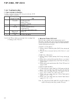
1. Power indicator LED states
Problems can be easily diagnosed by the power indicator (LED)
states of the display of the unit.
Note 1) The LED may blink in green instead of red according to the
PD timing or where PD occurs.
2. Abnormal Power Off Circuit
This unit comes equipped with various protection circuits.
When these protection circuit operates, P.D. (Power Down) operates
to turn off the relay (RL1) inside the POWER SUPPLY MODULE.
And turn off the power of the unit.
• X DRIVE (A) /(B) assembly
1) PD due to the over-current detection of the X drive power supply
V
CP
+12V
2) PD due to the over-current detection of the X drive (+) reset
circuit
• Y DRIVE (A) /(B) assembly
1) PD due to the over-current detection of the Y drive power supply
V
CP
+12V
2) PD due to the over-current detection of the Y drive (–) reset circuit
3) PD due to the over-voltage detection of the Y drive D-D converter
output V
H
150V
4) PD due to the over-current detection of the Y drive D-D converter
output V
H
150V
• POWER SUPPLY MODULE
1) PD due to the over-current detection of the large power supply
(V
SUS
+175V, V
OFS
+150V. V
CSP
+40V, V
RN
–190V, V
ADR
+30V).
2) PD due to the over-voltage detection of the large power supply
(V
SUS
+175V, V
CSP
+40V, V
RN–
190V, V
ADR
+30V)
3) PD due to the over-current detection of the small signal power
supply (+12V, +5V, +3.3V)
4) PD due to the over-voltage detection of the small signal power
supply (+12V, +5V, +3.3V)
Note) +5V is supplied to K2609 and K3109 of the PD terminal of
each drive assembly when drive assembly PD occurs.
State
Normally power ON
Display PD Note 1)
(Not remote controlled)
Display AC OFF
•
Power off by remote control
•
Auto power OFF
•
When internal temperature is high
Display PD
AC OFF of the display
Display LED State
Lit in green
Off
Lit in red
Blinking in red
0.5/0.5 sec
Off
1.
2.
3.
4.
5.
Summary of Contents for PDP-501MX
Page 16: ...PDP 501MX PDP V501X 16 A B C D 1 2 3 4 1 2 3 4 3 3 POWER SUPPLY MODULE 1 2 J 1 2 ...
Page 17: ...PDP 501MX PDP V501X 17 A B C D 5 6 7 8 5 6 7 8 J 1 2 ...
Page 18: ...PDP 501MX PDP V501X 18 A B C D 1 2 3 4 1 2 3 4 3 4 POWER SUPPLY MODULE 2 2 J 2 2 ...
Page 19: ...PDP 501MX PDP V501X 19 A B C D 5 6 7 8 5 6 7 8 J 2 2 ...


