44
PDP-503PE, PDP-503PU
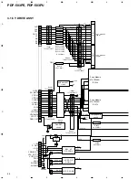
4.4V
1.6V
0V
7.3V
7.3V
0V
7.3V
7.3V
5.8V
5.9V
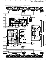
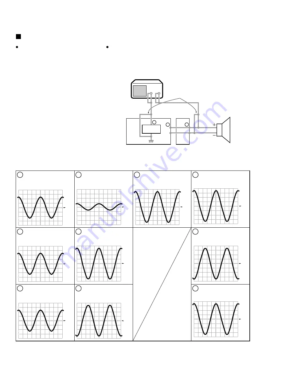
CH1
CH2
Oscilloscope
Measurement
Point
AUDIO AMP ASSY
SP TERMINAL ASSY
SP TERMINAL
ASSY
Speaker
etc.
AUDIO AMP
ASSY
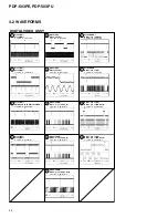
1
CN5001 - pin 4 (L)
↔
GND
V: 0.1V/div. H: 0.2msec/div.
2
IC5202 - pin 14 (LOUT)
↔
GND
V: 0.1V/div. H: 0.2msec/div.
4
IC5002 - pin 1 (IN1)
↔
GND
V: 0.1V/div. H: 0.2msec/div.
5
J5003 - pin 5 (L+)
↔
GND
V: 1V/div. H: 0.2msec/div.
3
IC5201 - pin 19 (FOCUSOUTL)
↔
GND
V: 0.1V/div. H: 0.2msec/div.
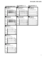
6
J5003 - pin 6 (L–)
↔
GND
V: 1V/div. H: 0.2msec/div.
7
J5003 - pin 5 (L+)
↔
pin 6 (L–)
V: 2V/div. H: 0.2msec/div.
8
CN5301 - pin 1 (L+)
↔
GND
V: 1V/div. H: 0.2msec/div.
7
1
10
9
CN5301 - pin 2 (L–)
↔
GND
V: 1V/div. H: 0.2msec/div.
10
CN5301 - pin 1 (L+)
↔
pin 2 (L–)
V: 2V/div. H: 0.2msec/div.
AUDIO SECTION
Video Input Signal : FULL FIELD COLOR-BAR
Audio Input Signal : 1kHz Sine Carve 0.2Vrms
Volume
: 60 (MAX)
AV Selection
: STANDARD
SRS
: OFF
FOCUS
: OFF
Measurement condition
GND and the speaker output (- side) becomes
a short state on the oscilloscope.
Wrong connection example
Caution in the measurement
Audio Power Amp. (IC5002: LA4628) on the AUDIO AMP Assy is BTL system, and,
as for the power amplifier and the speaker output,
±
poles becomes hot for the
ground. Therefore be careful not to connect the measuring instrument as the following
figures. (Power amplifier may be damaged.)


