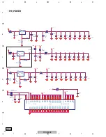
PDP-505MX
17
5
6
7
8
5
6
7
8
C
D
F
A
B
E
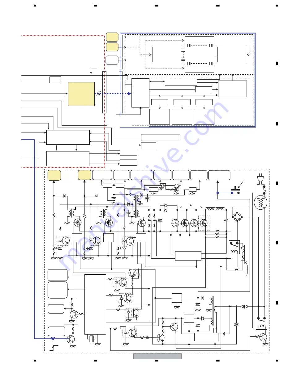
LVDS
DRIVER
U19
(EP387)
FAN Motor
controller U11
(G791)
IR Receiver/Front Key
LED
FAN1
ALRM
FAN2
FAN Motor Driver
U16,U17 (G994)
FG2
FG1
FAN 1
FAN 2
LVDS
CON18
PDP module Unit
Vd
Vs
I/Fcircuit
Color space
conversion
Inverse
gamma
correction
Error
diffusion
Frame memory
ON/OFF
ON/OFF
ON/OFF
ON/OFF
H; Lvds Recever Power on
L; shutdown
Control circuit
Color plasma
display panel
Data driver
Data driver
Scan driver
Sustain driver
OSD signal
RGB video signal
Logic Control Part
Display panel and Driver Part
CN101
LVP
CN301
Normal operation ; H
Abnormal ; L
+5
CN302
U25
LVPS
Adjustment of Vbw, Vsw1, Vp and Vsw2 on PDP module is necessary
Power Supply Unit
IC201
6
PFC:Power Factor Correction
RL01
RL02
IN
OUT
+7V (STB)
VDD
PC02
C05A
+
PFC
+
C09A
C09B
L05
VCC
R04
F5K100J14
Thermal Cutoff
Resistor
7
+
IC21 STR6169
D801
C22
Q26
Q25
IC22
+
C26
D25
OUT
D22
D21A D21B
T21
D92
+
C92
Q91
T41
T61
T71
IC92
IC41
IC61
IC71
PFCgo
VCCgo
Vsgo
Vdgo
50inchi :2SK3505x4
42 inchi:2SK3505x3
AC IN
FU
14
+5V
Q224
+5V
8
9
10
PC04
PC05
PC03
Q41
Q61
Q71
VR161
Vd-ADJ
VR151
Vs-ADJ
VR121
Vcc-ADJ
+5V
Q223
15
1
CPU
IC221
Main SW
(mechanical)
POMUT for
U10 reset
LVP signal
to PDP
Module
ALM
P-ON
Vd
Vs
A+12V
+6V
+3.3V
+2.5V
+7V(STB)
PC71
PC61
PC41
Q23
P-ON
VCC (+5V)
IC112
IC111
S+12V
IC131
IC101
S
D
Q131
Q132
Adjustment of Vd and Vs on
Power supply unit is
necessary when it's replaced
new one
not use
Summary of Contents for PDP-505MX
Page 7: ...PDP 505MX 7 5 6 7 8 5 6 7 8 C D F A B E ...
Page 21: ...PDP 505MX 21 5 6 7 8 5 6 7 8 C D F A B E ...
Page 46: ...PDP 505MX 46 1 2 3 4 1 2 3 4 C D F A B E Sensor Board IR Board Power Switch Board ...
Page 47: ...PDP 505MX 47 5 6 7 8 5 6 7 8 C D F A B E Button ...
Page 48: ...PDP 505MX 48 1 2 3 4 1 2 3 4 C D F A B E Audio Board ...
Page 49: ...PDP 505MX 49 5 6 7 8 5 6 7 8 C D F A B E ...
Page 50: ...PDP 505MX 50 1 2 3 4 1 2 3 4 C D F A B E PS250 PWR 500W ...


