PDP-505MX
69
5
6
7
8
5
6
7
8
C
D
F
A
B
E
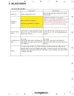
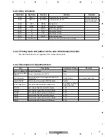
6.2.5.4 Timing mode and pattern for the auto white balance function
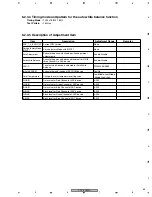
6.2.5.5 Description of Adjustment Item
Item
Description
Adjustment Range
PHX_1_0_BASIC_JP Current F/W Version
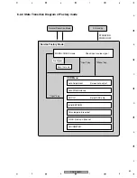
Service factory Mode
INPUT3
Service factory Mode with INPUT3
Auto White Balance
Execute the gains and biases adjustment for R/G/B
three Channels in ADC device
Enable/Disable
Initial EEPROM
Execute the initial setting of EEPROM device
Yes/No
Color Temperature
Change the color temperature setting value.
Low/Middle-Low/Middle
/Middle-High/High
R-GAIN
Gain value for Red Channel of ADC device
0~512
G-GAIN
Gain value for Green Channel of ADC device
0~512
B-GAIN
Gain value for Blue Channel of ADC device
0~512
R-BIAS
Black level for Red Channel of ADC device
0~512
G-BIAS
Black level for Green Channel of ADC device
0~512
B-BIAS
Black level for Blue Channel of ADC device
0~512
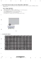
Timing Mode :
720 x483 @ 59.94 Hz (483p)
Test Pattern :
SMPTE COLOR BAR
6.2.6 To leave service factory mode:
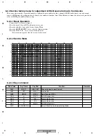
6.2.5.3 Key command
Rem Code
Key Name
Key Pad
Function
Remarks
AA56
INPUT 3
INPUT/SET
Choose the input to input Source 3
For basic model
AAD3+AF7B
INPUT 5
INPUT/SET
Choose the input to input Source 5
For custom model
AA8A
SET
MENU
Function Set
AA8B
MENU
MENU
Open/Close the MENU
AA96
RIGHT+
Select the upper item
AA95
VOL +
Execute the function
AA94
VOL-
Execute the function
AA97
RIGHT-
Select the lower item
AA1C
STANDBY/ON
Power Off and Exit the Service factory Mode
• AC power cord Pulled out.
Summary of Contents for PDP-505MX
Page 7: ...PDP 505MX 7 5 6 7 8 5 6 7 8 C D F A B E ...
Page 21: ...PDP 505MX 21 5 6 7 8 5 6 7 8 C D F A B E ...
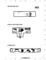
Page 46: ...PDP 505MX 46 1 2 3 4 1 2 3 4 C D F A B E Sensor Board IR Board Power Switch Board ...
Page 47: ...PDP 505MX 47 5 6 7 8 5 6 7 8 C D F A B E Button ...
Page 48: ...PDP 505MX 48 1 2 3 4 1 2 3 4 C D F A B E Audio Board ...
Page 49: ...PDP 505MX 49 5 6 7 8 5 6 7 8 C D F A B E ...
Page 50: ...PDP 505MX 50 1 2 3 4 1 2 3 4 C D F A B E PS250 PWR 500W ...

