57
PDR-509
[Procedure]
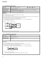
(1) Press the DIGITAL SYNCHRO button in Stop mode.
Note: Make sure the unit is in Stop mode.
(2) Check that "48" appears on the FL display.
(3) Press the AUTO/MANUAL button so that "04 34" appears on the FL display.
(4) Press the FINALIZE button for focus-in.
(5) Press the PLAY button for CAV-servo spindle kick.
(6) Press the PAUSE button to close the tracking servo, then set the unit to Playback mode.
(7) Adjust with the RDIGITAL REC LEVEL knob until the above adjustment value to be reached is obtained.
Press the DIGITAL REC LEVEL knob to register the adjustment. Once the adjustment is registered with the DIGITAL REC LEVEL knob,
"?" on the FL display will disappear.
(8) Press the STOP button to stop the unit.
Note: Adjustment must be done around mid-radius on a disc.
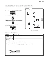
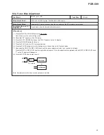
6.5.4 Focus Bias Adjustment
CN102 - pin 1 (RF)
Test Point
Adjustment Point
Adjustment Value
DIGITAL SYNCHRO button, DIGITAL REC LEVEL knob
Adjust until RF jitter is minimal or that the eye pattern of the RF waveform is most open.
Jitter Meter
10:1 probe
or
10 : 1
Oscilloscope
RF
VC
Symptom when out of
adjustment
Sound broken, record characteristics deteriorate
STD-903
Test Disc
Summary of Contents for PDR-509
Page 19: ...PDR 509 19 A B C D 5 6 7 8 5 6 7 8 CDR SERVO AMP MULTI PLEXER A1 5 A4 5 A3 5 A1 5 1 3 5 A ...
Page 43: ...PDR 509 43 A B C D 5 6 7 8 5 6 7 8 PNP1466 A Q701 Q704 PNP1466 A CN51 J SIDE A SIDE B I ...
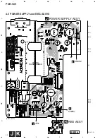
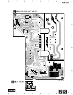
Page 45: ...PDR 509 45 A B C D 1 2 3 4 1 2 3 4 J K PNP1466 A POWER SUPPLY ASSY J REG ASSY K SIDE B ...
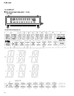
Page 68: ...68 PDR 509 FL TUBE 7 2 2 DISPLAY PEL1099 FUNCTION ASSY V701 Anode Grid Assignment 1 35 ...
Page 69: ...69 PDR 509 Pin Assignment ...
Page 73: ...73 PDR 509 MONITOR DIGITAL REC LEVEL ANALOG REC LEVEL INPUT SELECTOR TIME REPEAT ...


