70
PDR-509
7.3 EXPLANATION
7.3.1 ERROR CODE
Laser Hour Meter Indication and Error Code Display for Service
The PDR-509 can display the total turn-on time of the laser diode
and error codes for service.
When the STOP key is held down for about 5 seconds in stop
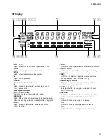
state in Normal mode, an FL display as shown below is obtained.
Left 4 FL digits
: Total turn-on time of the laser diode
Right 2 FL digits : Error code for service
The total turn-on time of the laser diode is displayed in the range
of 0 to 5100.
The error code for service is displayed as a number (ERROR
NUMBER), which follows a message "CHECK DISC" or
"CHECK." For details, see the table below.
To initialize the total turn-on time of the laser diode, hold the
STOP key down for about 5 seconds in stop state with the INPUT
selector set to analog in Test mode.
The message "CLEAR" is displayed, and the total time is cleared.
Display
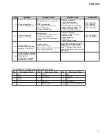
Error code table for service
Laser Hour Meter
indicationsplay
Error code Number
∗∗∗∗ ∗∗
Code
Symptom
Contents of Error
Possible Cause
Checkpoints
H0
No operation even when
power is supplied.
Communication between mechanism
controller and mode controller is not
achieved.
• Improper soldering
• Pattern short
IC301 (PE5109A)
IC351 (PDJ014A)
H1
(CHECK display)
Defective mechanism controller
terminals
• Short-circuiting of parts
• Improper power supply
IC371
(HD74HC573FP)
H2
Pre-recording process does
not complete, and the tray
does not open.
(CHECK display)
Improper input voltage at the
mechanism-control terminals
(pins 22, 23, 24)
IC201 (PA9007A)
H5
Pre-recording process
disabled (CHECK display)
Improper IC303 data writing
• Defect in IC303
IC303 (PYY1196)
L
∗
The unit stops during the
tray open/close operation.
(CHECK display)
Improper loading
• Defective tray position sensor
• Defective loading motor
• Improper soldering
• Pattern short
• Improper power supply
IC451 (M56788FP)
E
∗
The unit stops when PLAY
or REC/PAUSE starts.
(CHECK display)
Defective slider
• The pickup cannot be returned to the
specified position.
• Disconnected flexible cable
• Defective drive circuit
• Abnormal power supply
• Abnormal TOC position switch
• Improper soldering
S601 (PSG1013)
IC451 (M56788FP)
IC401 (CXD2585Q)
P
∗
The unit does not read the
inserted disc, and stops.
(CHECK DISC display)
Defect in spindle
• Disc upside-down.
• Dirty or cracked disc
• Abnormal disc rotation
• No signal obtained from the disc
• Defective spindle motor
• Defective spindle drive circuit
• Abnormal FG signals
• Defective WBL circuit
• Defective decoder circuit
• Unable to read ATIP or subcode
• High error rate
PC651
(NJL5803K-F1)
IC451 (M56788FP)
IC401 (CXD2585Q)
∗
1
∗
1
∗
1 : SERVO MECHANISM Assy
Summary of Contents for PDR-509
Page 19: ...PDR 509 19 A B C D 5 6 7 8 5 6 7 8 CDR SERVO AMP MULTI PLEXER A1 5 A4 5 A3 5 A1 5 1 3 5 A ...
Page 43: ...PDR 509 43 A B C D 5 6 7 8 5 6 7 8 PNP1466 A Q701 Q704 PNP1466 A CN51 J SIDE A SIDE B I ...
Page 45: ...PDR 509 45 A B C D 1 2 3 4 1 2 3 4 J K PNP1466 A POWER SUPPLY ASSY J REG ASSY K SIDE B ...
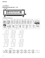
Page 68: ...68 PDR 509 FL TUBE 7 2 2 DISPLAY PEL1099 FUNCTION ASSY V701 Anode Grid Assignment 1 35 ...
Page 69: ...69 PDR 509 Pin Assignment ...
Page 73: ...73 PDR 509 MONITOR DIGITAL REC LEVEL ANALOG REC LEVEL INPUT SELECTOR TIME REPEAT ...

