10
PDR-609
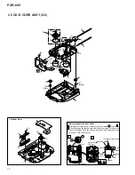
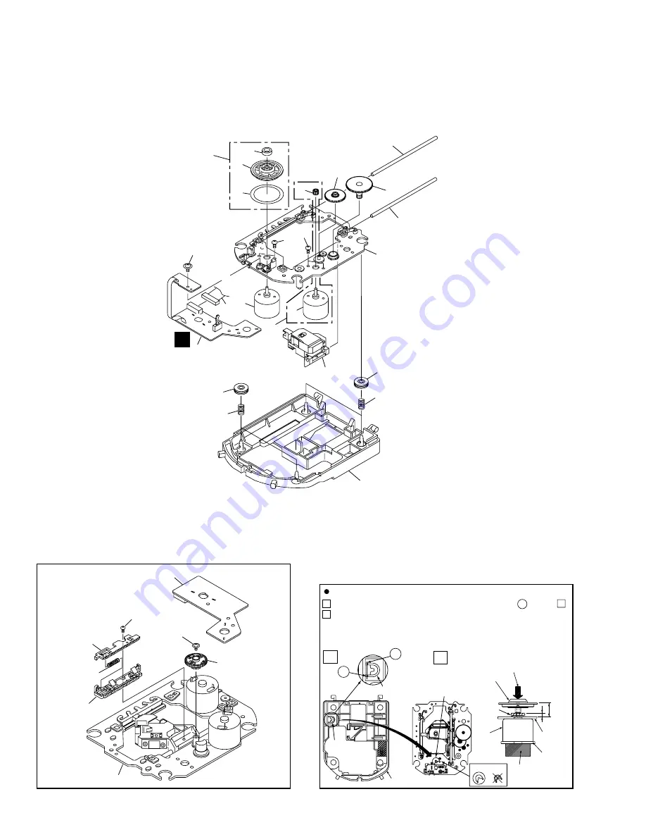
Use nippers or other tool to cut the two sections marked A in figure 1 .
While supporting the spindle motor shaft with the stopper, put spacer on
top of the carriage base, and stick the disc table on top (takes about 9kg
pressure). Take off the spacer.
Spacer
Spacer
OK
NG
A
2
1
2.8mm
11mm
Disc table Assy
(Pressure of about 9kg)
Carriage
Base
PCB
Stopper
Spindle
motor
Spacer setting
Position
Spacer
Servo Base
A
1
2
How to Install the Disc Table
11
20
15
7
25
21
4
8
18
19
16
2
22
To
CD-CORE
CN452
17
3
24
24
1
5
26
27
(Gray)
(Black)
4
9
10
24
1
12
14
22
16
6
13
•
Bottom View
C
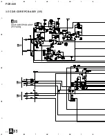
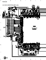
2.5 CD-R CORE ASSY (2/2)
Summary of Contents for PDR-609
Page 45: ...PDR 609 45 A B C D 5 6 7 8 5 6 7 8 G IC701 IC702 IC706 CN601 D SIDE A SIDE B ...
Page 73: ...73 PDR 609 Pin Function 2 5 ...
Page 74: ...74 PDR 609 Pin Function 3 5 ...
Page 75: ...75 PDR 609 Pin Function 4 5 ...
Page 76: ...76 PDR 609 Pin Function 5 5 ...
Page 80: ...80 PDR 609 AK8567 CD R CORE PCB ASSY IC101 RF Processor Pin Function 1 2 ...
Page 81: ...81 PDR 609 Pin Function 2 2 ...
Page 84: ...84 PDR 609 1 FL TUBE Grid Assignment Pin Connection PEL1101 OPERATING ASSY V701 7 2 2 DISPLAY ...
Page 85: ...85 PDR 609 Anode Connection ...


