53
PDR-609
-
0
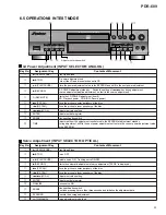
6.5 OPERATIONS IN TEST MODE
LD Power Adjustment (INPUT SELECTOR: ANALOG)
Servo Adjustment (INPUT SELECTOR: OPTICAL)
Key No.
Assignment Key
Contents of Movement
1
0
(OPEN/CLOSE)
Tray Open/Close
2
7
(STOP)
Servo OFF
3
6
(PLAY/PAUSE)
Spindle servo ON, Tracking servo ON/OFF
4
(RECORD)
Starts the automatic adjustment of servo adjustment ("FEOS" is displayed.)
6
¡
(F SCAN)
Move the pickup to outer periphery of the disc
7
1
(R SCAN)
Move the pickup to inner periphery of the disc
8
4
¢
(JOG
±
)
Adjustment value setting
9
ENTER
Adjustment data register
0
FINALIZE
Focus servo ON
-
ERASE
Disc specification switch
Continue pressing it more than three seconds and initialize the adjustment data.
~
SYNCHRO
Execute the average adjustment
!
AUTO/MANUAL
Servo adjustment mode feed
Key No.
Assignment Key
Contents of Movement
1
0
(OPEN/CLOSE)
Tray Open/Close
2
7
(STOP)
LD power adjustment end
Turn off the LD and disc selection set to CD.
3
6
(PLAY/PAUSE)
Store the power adjustment value to the EEPROM and shift to the next power adjustment.
4
(RECORD)
LD POWER adjustment standby Switch the setting of
4
•
¢
key during adjustment.
(coarse adjustment
j
fine adjustment : default is the coarse adjustment)
5
•
(REC MUTE)
Starts the LD POWER adjustment (from 0)
(CD: Playback power, CD-R/RW: Record power)
6
¡
(F SCAN)
Move the pickup to outer periphery of the disc
7
1
(R SCAN)
Move the pickup to inner periphery of the disc
8
4
¢
(JOG
±
)
Adjustment value setting
9
ENTER
Adjustment data register
-
ERASE
Disc specification switch
=
TIME
Adjustment from the adjustment result stored in the EEPROM at adjustment standby.
During adjustment, shift to the next power adjustmnet not to store the current power adjustment value
in the EEPROM.
◊ÛB
-
>?/
COMPACT DISC DIGITAL RECORDER
MONITOR
DIGITAL
REC LEVEL
ANALOG
REC LEVEL
INPUT
SELECTOR
AUTO
MANUAL
DISPLAY/
CHARA
MENU/
DELETE
TRACK NO.
WRITE
TIME
FINALIZE
ERASE
SCROLL
NAME
SYNCHRO
PUSH ENTER
R
L
ANALOG
REC BALANCE
Legato Link Conversion
CD TEXT
!
Adjustment mode switch
7
3
6
2
~
=
1
4 5
8 9
Summary of Contents for PDR-609
Page 45: ...PDR 609 45 A B C D 5 6 7 8 5 6 7 8 G IC701 IC702 IC706 CN601 D SIDE A SIDE B ...
Page 73: ...73 PDR 609 Pin Function 2 5 ...
Page 74: ...74 PDR 609 Pin Function 3 5 ...
Page 75: ...75 PDR 609 Pin Function 4 5 ...
Page 76: ...76 PDR 609 Pin Function 5 5 ...
Page 80: ...80 PDR 609 AK8567 CD R CORE PCB ASSY IC101 RF Processor Pin Function 1 2 ...
Page 81: ...81 PDR 609 Pin Function 2 2 ...
Page 84: ...84 PDR 609 1 FL TUBE Grid Assignment Pin Connection PEL1101 OPERATING ASSY V701 7 2 2 DISPLAY ...
Page 85: ...85 PDR 609 Anode Connection ...

