68
PDR-W839
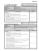
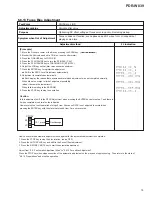
[Procedure]
1. Enter the Test mode.
2. Press the INPUT key so that "ANALOG" appears on the FL display.
3. Press the ERASE key so that "CD-RW" appears on the FL display.
4. Move the pickup to the position where the power is easy to measure by pressing the SCAN key.
(
41 ¡¢
)
5. Press the REC/REC MUTE and NAME key in order, and light the LD.
<Adjustment of CD-RW Bias Power>
6. Turn the JOG key to adjust the power.
Switch the coarse adjustment and the fine adjustment by pressing the REC/REC MUTE key, and adjust it.
(initial state is the coarse adjustment.)
7. Press the PLAY/PAUSE key to register the adjustment if the power became the adjustment value.
When it is registered, shift to the CD-RW Record Power Adjustment automatically.
Note: In the CD-RW Bias Power Adjustment, in the case that the power is over 2.3 mW when the LD
lighted, do not need to perform the Bias Power Adjustment. Set adjustment value of the CD-RW
record power to + 0.9mW
±
0.05mW against the power in LD lighting then.
<Adjustment of CD-RW Record Power>
8. Turn the JOG key to adjust the power.
Switch the coarse adjustment and the fine adjustment by pressing the REC/REC MUTE key, and adjust it.
(initial state is the coarse adjustment.)
9. Press the PLAY/PAUSE key to register the adjustment if the power became the adjustment value.
When it is registered, shift to the CD-RW Erase Power Adjustment automatically.
<Adjustment of CD-RW Erase Power>
10. Turn the JOG key to adjust the power.
Switch the coarse adjustment and the fine adjustment by pressing the REC/REC MUTE key, and adjust it.
(initial state is the coarse adjustment.)
11. Press the ENTER key to register the adjustment if the power became the adjustment value.
12. Press the STOP key to goes out the LD, and adjustment is completed.
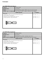
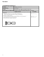
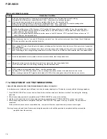
6.7.3 CD-RW Record Power Adjustment
RW Bias : 2.3 mW
±
0.05 mW, RW Rec : 3.2 mW
±
0.05 mW, RW Erase : 5.2 mW
±
0.1 mW
Pickup objective lens
Optimizing CD-RW recording power of laser diode.
Incapable of CD-RW recording, playing CD-RWs recorded on it. Sound pauses,
track skipping, or bad RF wave form (though no failure in playing CD).
Test Point
Adjustment Value
Purpose
Symptom when Out of Adjustment
Adjustment method
FL Indication
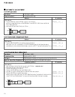
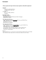
Cautions:
(1) All the reading values of power meter of this adjustment are values with an average.
(2) How to confirm the adjustment value:
When enter the power adjustment mode, enter it by pressing the REC/REC MUTE and DISPLAY keys in order.
Furthermore, can confirm the adjustment value of each power stored in EEPROM by switching the DISPLAY key.
However, RW cannot see all adjustment results. Use DAC the same as erase power in the Bias Power Adjustment, and
perform the adjustment of record power while outputting the setting value of erase power decided in the Bias Power
Adjustment. And perform the Erase Power Adjustment while outputting the setting value of the record power.
Therefore, the value of Bias Power Adjustment does not remain after adjustment of the erase power. (as for the displayed
adjustment value, erase power is the same as bias power.)
It is only erase power that can confirm the adjustment result with the power meter among power of RW.
As for the value of Record Power Adjustment, only setting numeric value is readable, but output power becomes the same
as the erase power.
Bias power cannot confirm the setting value, too. Be not used during actual record operations either.
DANGER – LASER RADIATION WHEN OPEN.
AVOID DIRECT EXPOSURE TO BEAM.
Summary of Contents for PDR-W839
Page 21: ...PDR W839 21 A B C D 5 6 7 8 5 6 7 8 3 5 A A 1 5 A 2 5 A 4 5 A 1 5 Servo Amp IC Multiplexer ...
Page 39: ...PDR W839 39 ...
Page 51: ...PDR W839 51 A B C D 5 6 7 8 5 6 7 8 H PNP1480 C SIDE A CN502 A 301 CN302 A ...
Page 53: ...PDR W839 53 A B C D 5 6 7 8 5 6 7 8 H IC601 Q492 Q401 Q428 IC1811 IC901 Q490 Q481 1 SIDE B ...
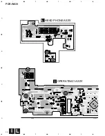
Page 56: ...PDR W839 56 A B C D 1 2 3 4 1 2 3 4 I L HEAD PHONE ASSY L OPERATING1 ASSY I IC701 Q708 ...
Page 94: ...94 PDR W839 Pin Function 1 5 PDC069 CD R CORE ASSY IC501 Encoder IC ...
Page 95: ...95 PDR W839 Pin Function 2 5 ...
Page 96: ...96 PDR W839 Pin Function 3 5 ...
Page 97: ...97 PDR W839 Pin Function 4 5 ...
Page 98: ...98 PDR W839 Pin Function 5 5 ...
Page 103: ...103 PDR W839 ...


