background image

Summary of Contents for PL-530

Page 1: ...t _ f_ l I I t _ Dr loNEER ...

Page 2: ...LFACILITIES 5 PARTS LOCATIONS 3 f TopView 7 3 2 BottomView 9 SCHEMATIC DIAGRAMS P C BOARDPATTERNS AND PARTSLIST 4 1 Stype SchematicDiagrams 11 4 2 Positional DetectorAssembly PWX 007 13 4 3 DriveControlAssembly PWG 009 14 4 4 Stype Power SupplyAssernbly PWR 821 17 EXPLODED VIEW 19 PACKING 30 NOMENCLATURE OFSCREW WASHER AND NUTS 31 D D MOTOR PXM O3OI OUTLINEOFOPERATION 32 1 2 3 l I 4 I 5 6 7 8 9 10...

Page 3: ...mentstylus PN 50 StylusTip 0 Smildiamond OutputVoltage 3mV at l kHz 50mm sRMS Tracking Force 1 5gto 2 19 properl lig Frequency Response 10 to 25 000H2 Subfunctions Anti skating forcecontrol Lateral balancer Styluspressure direct readout counterweight Cueing device Headshell stand Strobelight Freestophinges Accessories 45rpmadaptor I Overhanggauge 1 Screwdriver l Subweight t Operatinginstructions 1...

Page 4: ...nob while watching lhe strrrbemarks When this knob is turned in the direction thc spced incrcases rvhen turned in thc dircction the speeddecreases Reter to instructions ftrr FINE ADIUSTII IENT OF SPEED on page 0 45 RPM SPEEDFINE ADJUSTMENT KNOB Perf rm fine adjustment of 5 rpm speedwith this knoh while walching the slrobe marks When this knob is turned in the direction thc pecd incrc rscs whcn tur...

Page 5: ... record aurface caucing record and stylucdamage ARM LIFT LEVER Thetonearm israised andlowered withthislever UP Movingthc lcverto this position raises lhetonearm manuallv DOWN Movingthe leverto this positionlowers the tonearm manually Leavethe lever herelor aulomatic operation SELECTOR BUTTONS Purh this button to play the same record overand ovcr T lrelease thercpeatfunc tir n pushthcSTOPbulton FUN...

Page 6: ...3 PARTS LOCANON 3 1 TOPV EW Headshell stand PNW 073 Variablergistor PCS 008 Plate PxA 2 b D D Motor PXM oil Button unit i PAD OI4 panel PAN 036 ...

Page 7: ... WeightassemblY PXA 599 Knob ANTI SKATING PAA OI7 Panel PAN O32 Tonearmassembly PPD 546 Buttonunit REPEATI PAD OI6 assembly Buttonunit START STOP PAD OI5 ...

Page 8: ...3 2 BOTTOM VtEW lr I I E l 5 I F t f t t t Linevoltageselector PSB 001 Stype only Outputcord PDE 004 S ST rC tvpel PDE 016 KUtype Cabinet PMM 059 Stypel PMM 091 K typg PMM 064 STtype of PL 530X ...

Page 9: ...3 D D Motor j PXM o3O AC power cord PDG 004 Stypsl KDG 011 K type I qElD t r Gtc Powertransformer PTT 020 Stypel PTT 017 K type Powerzupplyassembly PWR 821 Stype PWR 820 K type Drivecontrol assembly h VG 009 rrrn 1H l j I t t 1 ar ...

Page 10: ...e 2SC9tt5xt 4 SCHEMATICDIAGRAMS P C BOARD 4 1 s type SCHEMATIC DIAGRAMS K typeonpose 401 I PosrfloNALi tETEcroR AssTi RESISTORS IN OHT1I 4W TOLERANCE UNLESS CAPACI TORS lN pF UNLESS 0THERWISE N0TED PATTERNS ANE DfiIVE TTROL Qre Qr 2SC I 0q 0t a 2SC94 2 POWER SU PLY I OTHERWISE NOTEDK KOI M 1 P PF PWX 00 l ...

Page 11: ...PT Drive control assemblY Positional detector a emblY Pouier supply assembtY S ST PorrrersuPPlYassemblY KCT KUT Microtwitch Microswitch Line voltage selector Neon lamP Timing motor Power transformer S tYPe I eower transformer K tYPe I I Speedselectorswitch I Sp a adiustment votume 1k B PWG 00 I nvx oo7 P1 VR 21 PwR 8zoI KSF 023 KSFO23 PSB 001 IPEL 0O5 I IPXM 037 IPTT 020 lrrr otr I IKsF 023 lPC900...

Page 12: ...09 No 5 P1 VR 821 B Part List RESISTORS PWG M9 PWG OO9 Symbol Descliption Part No R101 Rl02 R103 Rl04 Carbon film rk Carbon f ilm 1k Carbon film 1k Carbon film 330 RD7 PS1O2J RDTTPS1O2J RDy PS IO2J RD rPS331 1 OTHERS Symbol Dcrcription Part l o H1 H2 H3 Hall element Hall element Hall element PCX Ol2 PCX OI2 PCX 012 ...

Page 13: ... I i I I I I I l r L fl r t t L 4 3 DRTVE CONTROL ASSEMBLY PWG 009 t L J t o fi t ra GI oCJ c 3 y gqrtlu g i x o t 2 r c l i J r l J ...

Page 14: ...I I IA I I t i I i I I i I i i A PWX 007 No 3 PWX 007 No 6 PWX 007 No 1 PWX 007 No 7 B B c c PWX 007 No 1 PWR 821 G PWR 821 B P AIX 007 No 1 PWX 007 No 2 PWX 007 No 8 PWX 007 No 9 D SPEED SELECTOR SWITCH 33 r3 o t2 o t4 o 16 o 5 o 4 o ...

Page 15: ...M R234 Carbonf ilm 1Ok R235 Carbonf ilm 5 6k RD VS 6B2J RD VS lOOJ RDTTVS561J RD7 VS 82IJ RDY VS 1OOJ RD7 VS 682J RDY VS821J RD VS I13J RD7 VS 622J RD7 VS 123J RD7 VS 332J RD VS 155J RD7 VS I O3J RD VS 113J RD VS I33J RD VS 2O3J RDY VS392J RD7 VS 185J RD VS 1O3J RD VS 562J CAPACITORS Symbol Description Part No c1 c2 C3 c4 L3 Lu c8 c9 clo cl1 Ceramic lfi p 50V Electrolytic 4 7 25V Ceramic 100p 50V ...

Page 16: ...35V I CeA331p35 C4 i Eredrotytic 1OO ZSV I CEA I Olp 25 c5 ceramic 0 01 50V I CroYr to3z 50 C6 I Ceramic O O47 ZSOvI PCL OO5 Symbol Description Part No o1 o2 DI Transistor Transistor Brirlgerectifiers Zener diode 25D234 25C372 Y or 2SC945 P PCX O1O w2 192 or RD18E OTHERS rut I FUse Fuse 50OmA lJeat sink Fuse clip AEK O23 PEK OO4 KNA 582 K91 006 RESISTORS Symbol Description Part No H1 R2 Metal oxid...

Page 17: ...TOROBE LIGHT INEVOLTAGE LECTOR o oo oo oo o GM AC SWl r l_ _____ l__ _r o lo oo o o FUr 300 nA250V Cz0 033 SW 2 o oo e F _ 61 2s0234 2SC372 r2SC945 100 25 oo Fo o Cs 0 01 A A AC 11OV 120V 220V c 0 01 OV c c D D l I ...

Page 18: ...M 091 K tYPe PMM 064 PL 530x1 Headshellstand PNW 073 OCYI 4x10 Speedselector assembl PXA 197 l Name plate 5i fu S I ll ptate screw g g PNB 242 er PBA o4o gl RWS 3 1x10 I I I q t Part2 r Seepage23 PSA4x1O PT3x5 I Part I Seepage2 1 Sprins M PBK oto st u gtr Pr3x5 1 i I ls i A Holder Al enw rsa xl ...

Page 19: ...ef E32 056 l r l t i LA Eb strainreliefE32 056 l nrjA4 crrui r to u i l l Wdil i r soL u lll l1 lql pu prat assembry 4 l 4 g 5 PNB 064 pxA res liil l Functionlwerassembly PXA 196 Linevoltage selectorp r 5 PSB 0oilS tvTo4tvt Seb pase 26 9ftpggld tn i iil rT T Y g Qlws i io 6 g y t i i Uiil PBA o4o Hw3 1x13 Fg fushbuttonassemblY 4 c21 part t ffip PXA 248 2 SeePage24 gC J ffi Pfate i PBK Spring BK o1...

Page 20: ... PXA 206 EW2 PSA4xl0 DD motor PXM O30 hrt 10 Seepage29 Floloef n a PNw 204 H d sprins g 192 PBK W 1 rrJx6 g V Microswitch 1 KsF 023 M g 6e g8 PM2 6x25 Lever PXT 123 Lever PXT 122 EW3 Wireunit PXT I t8 STOPspring PBH 107 STARTspring PBH 106 PSA3x5 ...

Page 21: ...r I _ l PNW S46 fr washer n Ew3 PNB 519 Ew3 e r s Z switchfl t tiru 319 Ew3 f ffiff n 16ri 6zs __rilm ro 4A7 xG 6 _ Washer r r t h 7 PNB 528 _ yiT l tr ld __ _ B g l fiii Psrt s E im PNw 2oo Seepase28 Part8 Seepage28 6 5 4 A B c D 6 5 4 4 tt i t I Laner KNA l X t Spring PBH 7 sw2 6 PM2 6x6 NOTE Pars irdicstedin gren typecannotbesupplied PSA 3x5 ...

Page 22: ... greentype cannotbesupplied PT2 6x6 l f P C board holder 821 008 so g ttootu PSA4x10 RW3 1x10 Heat sink KNA 582 P C board holder 821 008 Powertransformer PTT 020 Stype PTT 017 K type Power supply assembly n R 821 Stype PWR 820 K typel ...

Page 23: ...blY PXA 248 Buttonunit ero ot s Button unit PAD O16 Ariglt Wireunit d n Lever dEx lll pruw 2oo ilI d F ewz Coller pttw toz e Lever ptrtw tga EW2 g Springq PBH O42 t z N tl1 f 2 rslNr VltI f lN 11111 i1 r S F AdY V Bffir PNW 199 S Ew2 ___ Lever PNW 201 Steel ball 24 ...

Page 24: ...Pr s3Cl PART 4 NOTE Partsindicatedin greentype cannotbesupplied Speedselectorassembly PXA 197 t I _i Microswitch KSF 023 PM3xi 2 rli I Screw PBA O4O Buttonunit including cup PAD O14 L i I I ___l ...

Page 25: ...catedin greentype cannotbesupplied Functionleverassemblv 196 a e t stpel ati P Wireunit PXT 180 EW2 B ffir y d I Cant A q Screw A KBA OO2 Y Plastic screw 3x12 A B c D A B c D J Fr J r L L L L L L L ti ti L tl i 26 r l l I l t t ...

Page 26: ... _ Lateral bar PLA 586 Screw PLA 567 Arm lift sheet assembly PXA 648 SF4x5 Arm lestunit PXT 527 o SF3x2 5 Arm leststand PLA 662 Special nut PLA 663 Mounting screw PBA 9O5 fj I h sF26x2 H Hr u H A prlng H PBH 505 6 Jl soz ffi il iiuo Headshell PXA 630 Nuts 871 653 L__ 1 ST KUT KCTtype with out cartridge ...

Page 27: ...I q q q I L I L L L L L L L L L L L PART 8 PART9 l i I i NOTE Partsindicatedin greentype cannotbesupplied Disc PXT 117 EW2 EV lever unit Nut PLA 174 Washer PNW 195 Plate PXT 118 1 I Altr t D EW2 2A ...

Page 28: ...10 NOTE Partsindicated in green typecannotbesupplied Uppercover PNW O59 Armaturecore PTL OOl Steelball PEF OO1 Thrustcatch PNW O11 Rubbercushion PNT OO2 D D motor PXM O3O PT2 6x6 PM2 6x30 PSA4x10 Crip PEC 029 PM2 6x6 B I g g Ir L I g ...

Page 29: ... Operating instructions PR8 044 Stype PR8 O48 STtypel PR8 045 K type Vinyl bag Protector PHA OlO Box PHN OO5 Cover PHN OO2 Protector Bl P56 603 Packing case PHG 156 Stype PHG 139 KUTtYPe PHG 140 KCTtype PHG 148 STtypeof PL 530X A Vinylbag H56 603 Vinyl bag n ii Protector B P56 603 L L t L L L t L L r Stopper KNK 4O3 ...

Page 30: ... 438 Subweight PLA564 tt EW Darcription Shape E typewasher lPfl ril FW Flatwasher ol SW Spring lock washer l N Nut OE PN Pushnut SF Slotted setscrew Flarpointl efl HS Hexagon socket headlessset screw ED ocw Oval countersunk head wood screw 45 RPMAdaptor KNK O55 Screwdriver KEX OO2 following symbolsstandfor screws washersand nuts asshown in explodedview typeonly Cartridgemountingscrews o nuts 2 was...

Page 31: ...or 33 U3 or 45 rpm rotation is applied to the base of Qrr It follows that so long as the rotor is DC power supply 18V F ine speedadjustment control 33 1 3 45 rpnr a t T I T I l T I t t r I l t r I L r I t r I L a r I r I L r I r r r 8 D D MOTOR PXM o3O OUTLINE OF OPERATION 8 1 STRUCTURE The PXM 030 is an external rotor type DC motor in which Hall effect elements are used to detect the rotor positi...

Page 32: ...ue 8 4 TEMPERATURECOMPENSATION The section which corrects the speed of rotation of the motor as the ambient temperature changes comprisesvaristors Do Dr Du Dr Ds to achievetemperature compensation o Do compensatesQtr If Do were not provided an increase in temperature would cause an increase in Q 1 collector current and a corre spondingincreasein Q u Q r Q o Qrr with a rise in the basepotential of ...

Page 33: ...izersection 2 Comparator 3 Orivecoil currentcontrolsection 4 Drivesection 5 Eackvollagedetectorsection Dr 0r V0l221lr2 N i 3ht li3F It I L RESISTORS tN 0Hf1 r 4S To f RAl tLEuNtEss oTHEiutsE N0TEDK ki H mr CAPALITORS lN pF UNLETS 0THERwISE N01EO P pF l i I ii i jtl H i tis t LII VOLIA X SELECTM s r ISTART REPI AI 34 ...

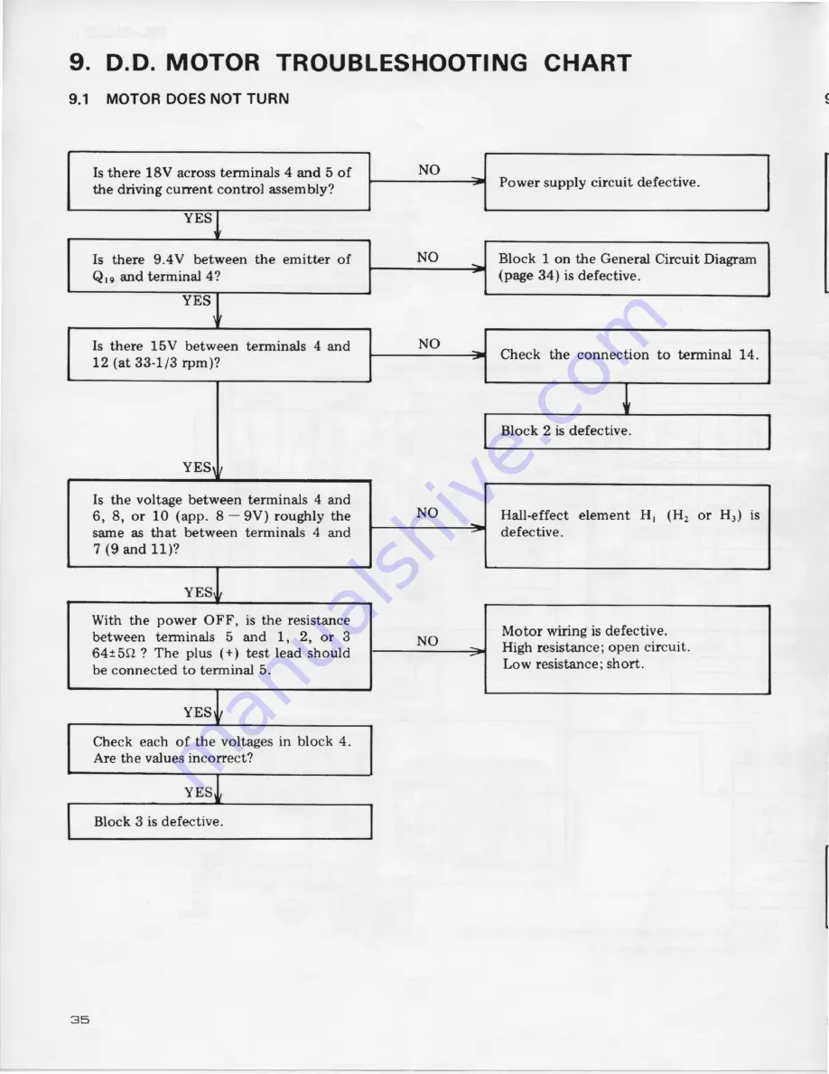
Page 34: ... at 33 1 3rpm Check the connection to terminal 14 Block 2 is defeetive Is the voltage between terminals 4 and 6 8 or 10 app I 9V roughly the same as that between terminals 4 and 7 9 and 11 Hall effect element H Hr or Hr is defective With the power OFF is the resistance between terminals 5 and 1 2 or 3 64tbQ The plus test lead should be connected to terminal 5 Motor wiring is defective Highresistan...

Page 35: ...11 Hall effect element Ht Ht or H3 is defective With the power OFF is the resistance between terminal 5 and 1 2 or 3 equal to 64t5O The plus test lead should be connected to terminal 5 Motor wiring is defective High resistance open cir cuit Low resistance short Disconnect the diodes of block 5 Dr D2 and D3 and check them with a test mef er Are they conductive in for ward direction or non conductiv...

Page 36: ...3 and 45 rpm adjustments Use a small screwdriver to tum these preset controls to give synchroniza tion as indicated by the stroboscopie speed indicator on the record player 3 When even turning the controls fails to give the required adjustment refer to Schematic diagam on page12 and change R223 33 1 3 rpm and R22e 45 rpm within the range1 5ksl to 5 6k4 before repeatingthe adjustment Check the conn...

Page 37: ...10 MECHANISM OPERATION UpperView O Tonearm 0 ptaten Timingmotor D D motor ...

Page 38: ...PL EigO BottomView o fl m o O wirec O Wire R e Ptate M ib Ptate o PtateF 0 PlateC 1f PlateE l PlateB t1 PlateG il4 PlateJ J5 CamA ...

Page 39: ... cam A rotation continues plate D moves tonearm to specified position and plate D stops Fig a Fig 4 7 As cam A rotation continues further plate C rotation continues and plate E disengages from plate F pin Step 5 freeing the tonearm Fig 5 Fis 5 8 Slantedsection of plate C lowers tonearm stylus onto record Fig 6 I I l l r I t G PlateB Fig 2 4 When plate C rotates due to cam A rotation friction plate...

Page 40: ...atter pin Fig 9 Irr 53cl 4 When the stulus movement exceeds3mm per record rotation the platter pin ehgagesplate H rig 10 Fis l0 5 When plate H is moved by the platter pin plate J and plate K are moved via plate G closing microswitch B and TM operates Fig 11 Fig 11 6 Accompanying TM rotation cam A rotates 7 Shorting switch shorts the cartridge output and plate C rotation raises the tonearm from the...

Page 41: ...witchB Fis 15 I 1 l r wire B in the t l V pulls ON MicroswitchA PlateA REPEATbutton Lock Fig 14 2 For this reason sinee microswitch A remains ON even at the end of such operations as auto teturn auto lead in and other operations be come performed again Microswitch circuit system Microswitch A Microswitch timingchart Microswitch AoN 5r oFF Microswitch BoN Sz OFF STOPT Operationf STOP srdntstatt Aut...

Page 42: ...teL and stopperanglecontact Fig 19 per hole posi posi Clockwise 11 3 ELEVATION 1 When ARM ELEVATION Fig 19 lever is DOWN so that flat section l d adjust by tuming screw A and metal plate are firmly in Fig 20 in contact asshown 2 Adjust scre M B so that elevation movement amount becomes the sarne for both manual and automatic operation 3 When elevation is UP stylus and record surface separationshal...

Page 43: ...ction Position 1 Setmechanismfor end of play condition 2 With cartridge stylus 64mm from center shaft so that tip screw of plate F and plate G contact adjusttip screw fig 21 b 11 5 DEFECTIVETONEARM OPERATION l Measure plate D torque during auto retum and lead in operations 2 Measuring position is 40mm from plate D center rotation shaft Turn adjusting nut so that torque at this time becomes40 to 60...

Page 44: ...n in Fig 24 becomes2mm s0 Adiustscrew Fis 24 11 8 REPEATBUTTON LOCK 1 Set for stop mode 2 When REPEAT button is pressed tum adjusting screw so that plate A locks the microswitch in the ON position Fig 25 Adiust screw Fig 25 11 9 PLATTER HEIGHT 1 Adjust4 screws so that spacing betweenplatter andcabinet becomes 2 5mm Fig 26 Adiustscrew riffi E 6 I r i r7V777WWi bin t Fis 26 ...

Page 45: ...osrroNAL I trrEcroR Assy rcwER SUPPLY A y PwR 8t4 i __ i ar250234 3r2SC3l2y2SCSrlS f PWX 001 Ftsl ij rF3 rN Crin l 4w tu rRAN u trE s CAPALI IOR9 tN 7rF UNLEIS 0rHrRV t5E NtjrEO OIHERTi ISE NOIELI K K 1 I1J P PI a _ b Or OI g l_ lrlr lr lr l l l r l l f r f r r J r__r r_J r_r rm ...

Page 46: ...FL Ei3Cl 13 K type PowER suPply ASSEMBLy pwR gzol A TIMINGMOTOR STROBELIGHT FUr 300rn o ossSW2 ...

Page 47: ...S Symbol Description Part No c1 c2 c3 c4 c5 Ceramic 0 033 250V Ceramic 0 033 25OV Electrolytic 330 35V Electrolytic 1O0 25V Ceramic 0 01 50V KCE 009 KCE O09 cEA 331P35 cEA 101P 25 CKDYF10325 RESISTORS Symbol Dercription Part No B1 R2 Mstal oxide Carbon film 10k 2w 3 3k RS2P IO3J RD PS332J OTHERS Symbol Description Part No FUl FU2 Fuse 3O0mA Fuse 500mA Heat sink Fuseclip E21 030 PEK OO4 KNA 582 K91...

Page 48: ......

Reviews: