background image

Summary of Contents for pl-930

Page 1: ...u gratis aangeboden door Pick upnaalden nl Web www pickupnaalden com Email info pick upnaalden nl Facebook www facebook com pickupnaalden Twitter twitter com Pickupnaalden Google https plus google com FCaris_pickupnaalden ...

Page 2: ...el WB 220V 240V United kingdom model WP 220V 240V Oceania model R 11OV 12OVl22OV 24OV Switchabte General export model R G 110V 12OV l22OV 24OV switchabte U S military model PIGINEEFI ELECTFICINIC CCIFIPCIFIATICIN 4 t Mesuno 1 chome Mesuno ku Tokyo ls3 Japan PIONEEFI ELECTFICINTCS IUSAI lNC 1925 E Dorninguez St Long Beach Catifonnia gO81O U S A PIONEEFI ELEcrFloNlc EuFloPEl N v Luirhagen Heven g eo...

Page 3: ...tions Full auto mechanism Anti skating force control Stylus pressure direct readout counterweight Cueing device Freestophinges Miscellaneous PowerRequirements WE WB WPmodels AC22O 24OV 50 60H2 R R G models AC11G120 22O 24OY switchablel 50 60H2 PowerConsumption 1AN Dimensions 420 W x 108 H x 367 D mm 16 112 wl x 4 1 alHl x 14 7116 Dlin weisht 5 9ks 131b PC 3MC Specifications T y p e M o v i n g c o...

Page 4: ...Ol24OVI Pon rtransformer 1110 120V 1220 240V1 Powercord Strainrelief Strainrelief ACcord Linevoltageselector Operating instructions Packingcase Top protector PUcord Powersupplyassembly Controlassembly LED assembly PNX 346 PAMO74 PADO85 PAD O86 PADO87 PAD 088 pie osz PSF 020 PTT I19 PDG 023 PEC 056 PEC 058 PRB 188 PHG438 PDE T4 xwRo05 xwvt 56 XWX 061 PNX 461 PAM 087 PAD 097 pno ioo PAD O99 pno oge ...

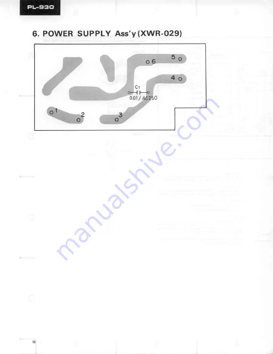
Page 5: ... moving itemc are indicated with the marhs and GENERALLY MOVES FASTER THAN This clasification shall be aQjustedby each dietributor becauseit depends on modelnumber tempetature humidity etc 560a 56 x 101 47ha 47 x 103 PowerSupplyAssembly XWR 024 CAPACITOR Mark Part No 661 RD PS6EilE J 473 RD PSEAE F J PowerSupplyAssembly XWR 029 Mark PartNo Symbol Deecription A PcL 041 ControlAssembly XWM 0851 SWIT...

Page 6: ...Ej 4 P C BOARD lrl CONNECTION DIAGRAM 3 L t MOTOR Ass v PWM O6 POWER TRANSFORMER D 2 I l_ ...

Page 7: ...5 BRN V HT BLU YEL BLK D 5O 60 A2 lo I POWER SUPPLY Ass y X ryR O24 d J ...

Page 8: ... o 2 4 SWITCI ES 5 1 P O W E R O N O F F S 2 S P E E D 3 3 7 3 r p m 4 5 r p m Theunderlined indicates theswitchpositio 3 2 1 OPERATI NG POINT AOJ 33 r e m P C P O 5 2 OPERATING POINTAOJ 45r p m P C P 0 5 2 CRYSTAL PSS O33 I v00 x l x 2 4 S B 5 R r 6 t 5 F OUT l 4 ST 45 33 il x cR t 0 t 2 t M OUT a 9 sP2 vccz z t a t O sP LocK 7rro 6 l l RT V OUT RFV REF sfoP CT FGIN 3 t 4 CHF FGOU 2 t 3 CHP FGREF...

Page 9: ...g point The I mark found on some component pans indicatc the im portance of the safety factor of the pan Therefore when replacing be sure to use parts of identical designation This is the basic schematic diagram but the actual circuit may v ry due to improvements in design PA2007 PD1003 frrl qlrt ruJil 0 4fl ___ 2SD985 lc la rl rvoe no _ vof fzn ffil r ot r ro tt l lt1l il E c q 2SC245A J ffi B I ...

Page 10: ...6 POWERSUPPLYAss y XWR O291 ...

Reviews: