PRS-D2000T/XU/UC
31
5
6
7
8
5
6
7
8
C
D
F
A
B
E
7. GENERAL INFORMATION
7.1 DIAGNOSIS
7.1.1 DISASSEMBLY
1
1
-
Removing the Case (Fig.1)
-
Removing the Amp Unit (Fig.2)
Remove the two screws.
Remove the six screws.
Fig.1
Fig.2
Case
2
Remove the nine screws.
2
Remove the five screws and then
remove the Case.
2
2
2
2
1
2
1
Amp Unit
1
1
2
2
1
1
1
1
2
2
2
2
2
2
2
Disconnect the connector and then
remove the Amp Unit.
Summary of Contents for PRS-D200/XU/EW5
Page 5: ...PRS D2000T XU UC 5 5 6 7 8 5 6 7 8 C D F A B E 1 SPECIFICATIONS ...
Page 17: ...PRS D2000T XU UC 17 5 6 7 8 5 6 7 8 C D F A B E ...
Page 21: ...PRS D2000T XU UC 21 5 6 7 8 5 6 7 8 C D F A B E SIDE B A IC602 1 1 8 9 16 CN630 1 1 C CN631 ...
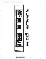
Page 32: ...PRS D2000T XU UC 32 1 2 3 4 1 2 3 4 C D F A B E 7 1 2 CONNECTOR FUNCTION DESCRIPTION ...
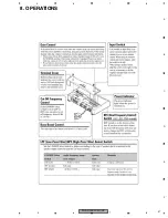
Page 37: ...PRS D2000T XU UC 37 5 6 7 8 5 6 7 8 C D F A B E 8 OPERATIONS ...
Page 38: ...PRS D2000T XU UC 38 1 2 3 4 1 2 3 4 C D F A B E ...


