PRV-LX10
156
1
2
3
4
1
2
3
4
C
D
F
A
B
E
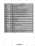
Operation
Symptom
Check Item
Measures to be taken
Misc
No operation possible with a USB device
(mouse/keyboard) connected to one of the
USB connector on the front panel
Check the connections:
The LED (D681) for the power supply on the USBB remains unlit:
Disconnect the USBB (CN684) connector.
→
No DC voltage applied to the PWRB connector pin
Disconnect the USBB (CN684) connector.
→
DC voltage applied to the PWRB connector pin
Check the USB signal.
Check the connections between the PWRB and USBB, and the MB and USBB.
Reconnect or replace the 3-pin cable (DKP3655) for power supply between the PWRB (CN5) and USBB (CN684).
If it is suspected that the PWRB (DWZ1129) is defective, replace it.
If it is suspected that the USBB (DWZ1159) is defective, replace it.
Reconnect or replace the 10-pin cable (DKP3646) for USB communication between the MB and USBB (CN681).
If it is suspected that the MB (DXF1007) is defective, replace it.
If it is suspected that the USBB (DWZ1159) is defective, replace it.
Control from an external device through
RS-422 impossible
Check the connections:
The LEDs (D7925, D7926, and D7927) for the power supply on the JKDB remains unlit:
Disconnect the JKDB (CN7902) connector.
→
No DC voltage applied to the PCIB connector pin
Disconnect the JKDB (CN7902) connector.
→
DC voltage applied to the PCIB connector pin
Check the settings and connected devices.
Check the connections among the PCIB, JKDB, and 422IB:
Reconnect or replace the 11-pin cable (DKP3642) between the PCIB (CN2102) and JKDB (CN7902).
If it is suspected that the PCIB (DWP1081) is defective, replace it.
If it is suspected that the JKDB (DWZ1134) is defective, replace it.
Reconnect or replace the 6-pin cable (DKP3644) between the JKDB (CN7903) and 422IB (CN7952).
The external RS-422 device may be one that cannot control this unit.
→
Refer to the Web site of Pioneer.
Control of an external device through
RS-422 impossible
Check the connections:
The LEDs (D7925, D7926, and D7927) for the power supply on the JKDB remains unlit:
Disconnect the JKDB (CN7902) connector.
→
No DC voltage applied to the PCIB connector pin
Disconnect the JKDB (CN7902) connector.
→
DC voltage applied to the PCIB connector pin
Check the settings and connected devices.
Check the connections between the PCIB and JKDB:
Reconnect or replace the 11-pin cable (DKP3642) between the PCIB (CN2102) and JKDB (CN7902).
If it is suspected that the PCIB (DWP1081) is defective, replace it.
If it is suspected that the JKDB (DWZ1134) is defective, replace it.
The external RS-422 device may be one that this unit cannot control.
→
Refer to the Web site of Pioneer.
LAN communication impossible
Check the connections.
Check the settings.
The LINK LED (yellow) corresponding to the LAN terminal does not light.
Connect the unit to a router, etc. with a straight cable.
If NETWORK is set to OFF, set it to ON.
If it is suspected that the MB (DXF1007) is defective, replace it.
No operation of DVD-DRV1
DRV2 operates instead of DRV1
Check the connections.
Press [FUNCTION] key then check the lower-right part of the screen to see if the connected
drives are recognized.
Check if the correct keys are pressed.
Check the connections between the MB and DVD_Drive 1, and between the ATX power supply and
DVD_Drive 1.
Reconnect the 4-pin power cable for the DVD-Drive 1.
Reconnect or replace the IDE cable (DKP3671) between the MB and Drive 1.
If it is suspected that the DVD Drive 1 (DVR-105-PLX) is defective, replace it.
Reconnect or replace the 6-pin FFC (DDD1231) that connects the FLKB (CN502) and DRV1B (CN631).
No operation of DVD-DRV2
Check the connections.
Press [FUNCTION] key then check the lower-right part of the screen to see if the connected
drives are recognized.
Check if the correct keys are pressed.
Check the connections between the MB and DVD_Drive 2, and between the ATX power supply and
DVD_Drive 2.
Reconnect the 4-pin power cable for the DVD-Drive 2.
Reconnect or replace the IDE cable (DKP3671) between the MB and Drive 2.
If it is suspected that the DVD Drive 2 (DVR-105-PLX) is defective, replace it.
Reconnect or replace the 6-pin FFC (DDD1231) that connects the KEYB (CN602) and DRV2B (CN641).
Key input disabled, or malfunctioning
Check the connections:
It is suspected that the key signals from another device remain to be input to FL UCOM
(IC501) and that signals from the corresponding keyboard are not accepted.
Check the key input from the remote control unit for service:
As each segment on the FL display corresponds to a particular key on the remote control
unit for service.
If any segment on the FL display was already unlit, there had already been key input.
Check the connections among the FLKB, KEYB, DRV1B, and DRV2B:
Reconnect or replace the 25-pin FFC (DDD1232) that connects the FLKB (CN503) and KEYB (CN601).
Reconnect or replace the 25-pin FFC (DDD1232) that connects the FLKB (CN503) and KEYB (CN601).
Reconnect or replace the 6-pin FFC (DDD1231) that connects the KEYB (CN602) and DRV2B (CN641).
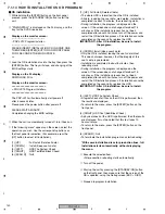
To enter Front-Panel-Button-Input Test mode, press the [ESC], [TEST], then [TV/LDP] keys, in that order.
To quit Test mode, press the [ESC] key.
Repair/replace the Assy corresponding to the inoperable key.
FLKB (DWZ1164): STB, Disp, Func, Function operations (
×
5)
KEYB (DWZ1157): Drv_Sel, Preview, Main operations (
×
8)
DRV1B (DWZ1160): Drv1_Eject
DRV2B (DWZ1161): Drv2_Eject
Repair/replace the Assy.


