11
En
Installation and Connections
Français
English
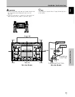
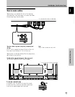
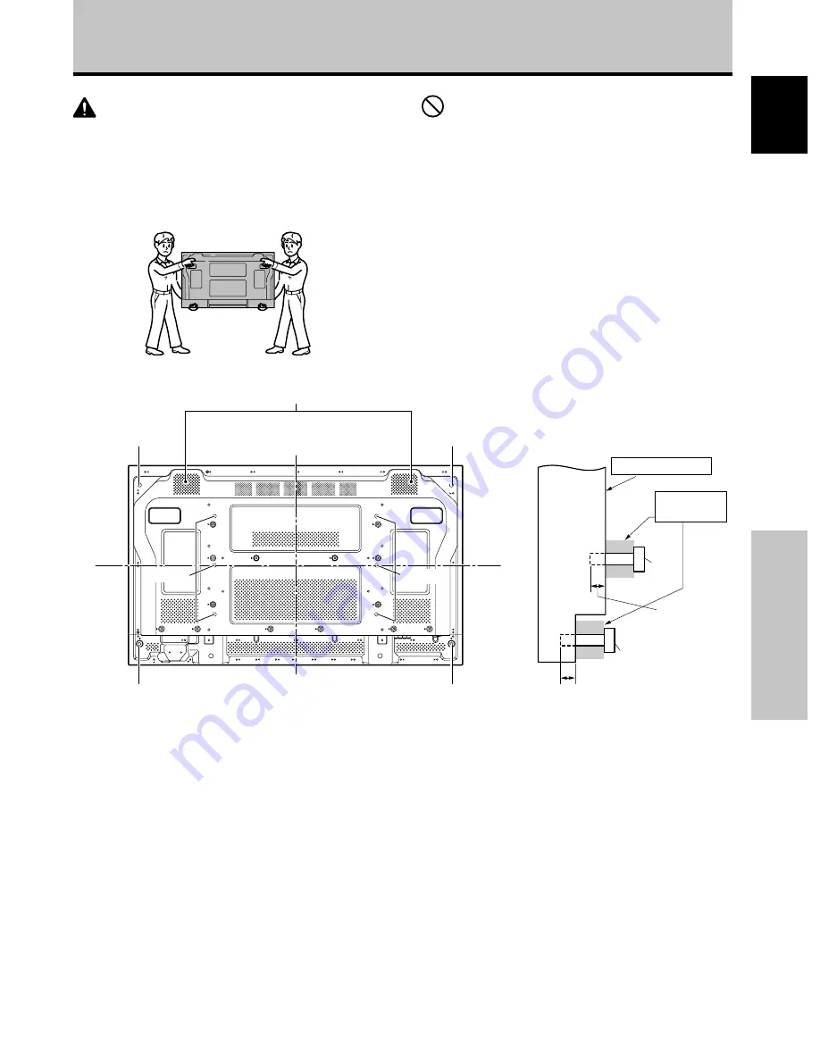
b hole
Main unit
Center line
b hole
b hole
b hole
Center line
a hole
b hole
Bolt
Bolt
Attaching surface
Installation
bracket, etc..
12 mm to 18 mm
(
1
/
2
in. to
11
/
16
in.)
12 mm to 14 mm (
1
/
2
in. to
9
/
16
in.)
Rear view diagram
Side view diagram
a hole
a hole
Installation and Connections
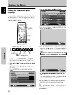
Air vents (fan)
CAUTION
÷
Handles should not be removed or reattached by anyone other
than the professional installation technician or service
personnel.
÷
When moving the display, it should always be carried by two
persons holding the rear handles in the manner shown.
NO!
Never attempt to move the Plasma Display by holding only one
of the handles.

