background image

36

En

Additional Information

English

Additional Information

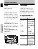
Cleaning

Regular cleaning will extend the life and performance of
this unit. The recommended way to clean the display and
related parts is described below.

Before cleaning, be sure to unplug the power cord from
the power outlet.

Cleaning the display panel body and remote
control

Do not under any circumstances use solvents such as
benzine or thinner for cleaner. Use of such liquids may
cause deterioration or peeling of paint from the display or
remote control unit.
Wipe the display and remote control gently with a soft
cloth. In the case of excessive dirt buildup, dampen a soft
cloth with a diluted neutral cleaning detergent and after
wringing the cloth thoroughly, wipe the component and
then dry it with a dry soft cloth.

Cleaning the screen

After dusting, wipe the screen gently using the supplied
cleaning cloth or another soft cloth (cotton, flannel, etc.).
Do not use tissue or a rough cloth. As the surface of the
screen is easily scratched, do not rub it or hit it with a
hard object.
If you clean the surface of the screen with a wet cloth,
water droplets on the surface may enter into the product,
resulting in malfunction.

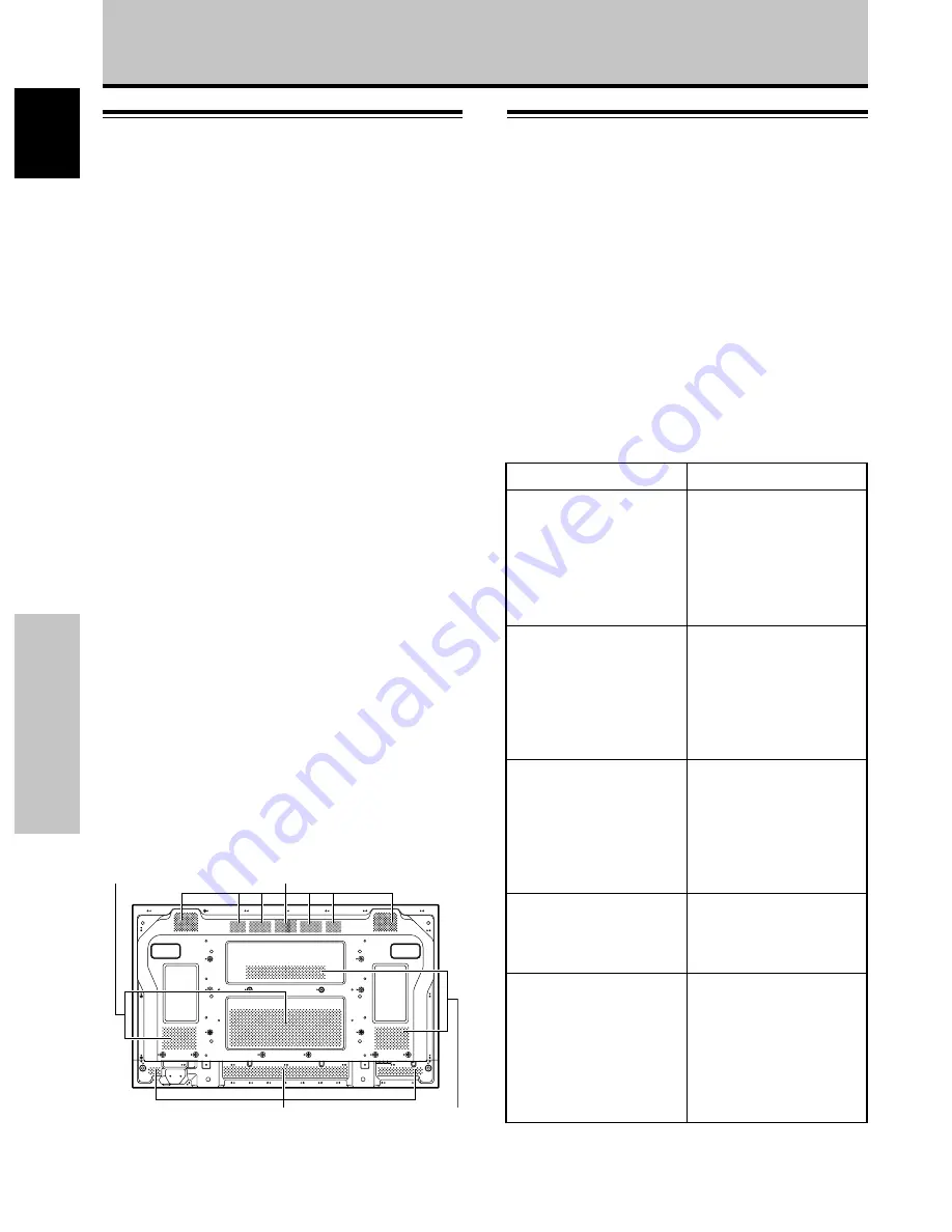
Cleaning the vents

As a general rule, use a vacuum cleaner about once a
month to clean the vents on the rear panel of the display
of dust buildup (set the vacuum cleaner to its weakest
setting when doing this).
Using the unit without cleaning it of dust will cause the
internal temperature to increase, resulting in possible
breakdown or fire.

Troubleshooting

What may at first seem to be an malfunction, may be
remedied with a quick check.
Please check to see if a warning is displayed on the
screen. If displayed, refer to the table below and check
the mode. If there is no display check to see if the
problem is listed on page 37. The problem may also be
caused by something other than this unit so please also
check the other components being used such as a video
deck. If the problem can still not be solved please consult
the dealer where this unit was purchased.

About the self diagnosis mode

Messages appear on the bottom of this unit’s screen to
indicate operation or connection faults. After message
confirmation, check the condition of the unit.

In the above, messages contents indicated by (**)
represent numerals.

ERROR MESSAGE

CAUTION

OUT OF RANGE

or

CAUTION

UNSUPPORTED SIGNAL

or

SIGNAL NG

WARNING

THERMAL ALERT

SHUT DOWN (**)

WARNING

FAN FAILURE

SHUT DOWN (**)

ERROR

INVALID KEY ENTRY

SHUT DOWN (**)

REMEDY

The current input signal is

not supported by the unit.

Check the Computer signal

compatibility table on

pages 40 to 42, and change

the computer’s output

signal setting appropriately.

Turn off main power (page

9).

Is ambient temperature

too high?

Remove any objects

blocking the cooling vents

on the Plasma Display.

Cooling fan has

malfunctioned.

Immediately turn off

power, remove power plug

from its outlet, and consult

a Pioneer service center or

your dealer.

An invalid operation has

been attempted. Check

input signals, connections

and other settings.

Turn off main power, wait

for 1-2 minutes, then try

turning power on again. If

problem persists, remove

power plug from its outlet

and consult a Pioneer

service center or your

dealer.

Vents

Vents

Vents

Vents

Summary of Contents for Pure Vision PDP-425CMX

Page 1: ......

Page 2: ......

Page 3: ...u will find it useful in the future Notes on Installation Work This product is marketed assuming that it is installed by qualified personnel with enough skill and competence Always have an installation specialist or your dealer install and set up the product PIONEER cannot assume liabilities for damage caused by mistake in installation or mounting misuse modification or a natural disaster Note for...

Page 4: ...sonable protection against harmful interference in a residential installation This equipment generates uses and can radiate radio frequency energy and if not installed and used in accordance with the instructions may cause harmful interference to radio communications However there is no guarantee that interference will not occur in a particular installation If this equipment does cause harmful int...

Page 5: ...on an unstable cart stand tripod bracket or table The product may fall causing serious injury to a child or adult and serious damage to the product Use only with a cart stand tripod bracket or table recommended by the manufacturer or sold with the product Any mounting of the product should follow the manufacturer s instructions and should use a mounting accessory recommended by the manufacturer CA...

Page 6: ...st Pioneer Authorized Independent Service Company or if you wish to purchase replacement parts operating instructions service manuals or accessories please call the number shown below 8 0 0 8 7 2 4 1 5 9 Please do not ship your product to Pioneer without first calling the Customer Support Division at the above listed number for assistance Pioneer Electronics USA Inc Customer Support Division P O B...

Page 7: ...larging one part of the screen POINT ZOOM 21 Multiscreen display 22 Automatic power off POWER MANAGEMENT 23 PICTURE SCREEN Adjustment 24 PICTURE adjustment 24 Adjusting screen POSITION CLOCK and PHASE automatic adjust 25 Adjusting screen POSITION CLOCK and PHASE manual adjust 26 Other Operations 28 Setting the ORBITER 28 Setting the SOFT FOCUS 29 Energy saving settings ENERGY SAVE 30 Automatic inp...

Page 8: ...ze settings supported include DOT BY DOT 4 3 and FULL 1 Supported signals are different on INPUT1 and INPUT2 1 Aspect ratio and screen size appearance will differ depending on input signal Free Installation Configuration Broader installation possibilities with thinner lighter high endurance design While producing a large 42 screen image the display is only 98 mm thick and weighs in at only 30 5 kg...

Page 9: ...ll the necessary points regarding installation of the Plasma Display and connections to a wide variety of components The section System Settings starting on page 16 covers the on screen settings necessary for correct operation of the Plasma Display with its connected components Depending on the connections made this section may or may not be necessary The remainder of the sections in this manual i...

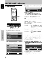
Page 10: ...ure can be seen clearly BRIGHTNESS Adjust so that the dark parts of the picture can be seen clearly H ENHANCE Sharpens the image in the horizontal direction V ENHANCE Sharpens the image in the vertical direction To reset PICTURE mode settings to the default If settings have been adjusted excessively or the picture on the screen no longer appears natural it may prove more beneficial to reset the PI...

Page 11: ...loth for screen 5 Speed clamps x 5 6 Ferrite cores x 2 for power cord Before Proceeding 7 Ferrite cores x 3 for audio cables 8 Display stands x 2 9 Washers x 2 0 Hex hole bolts x 2 Remote control unit holder Cable ties x 2 These Operating Instructions Warranty Use as a holder for the remote control unit When attaching to the rear of the main unit be careful not to cover the vents ...

Page 12: ...When the unit is in standby mode The indicator lights red page 18 When flashing the indicator is used to indicate error messages page 38 5 Handles Operation panel on the main unit 6 STANDBY ON button Press to put the display in operation or standby mode page 18 7 MENU button Press to open and close the on screen menu pages 16 to 35 8 DISPLAY SET button Use to confirm onscreen menu selections and t...

Page 13: ...mputer signal input automatically sets the POSITION CLOCK and PHASE to optimum values page 25 STANDBY ON button Press to put the unit in operation or standby mode page 18 DISPLAY button Press to view the unit s current input and setup mode page 19 POINT ZOOM button Use to select and enlarge one part of the screen page 21 FREEZE button When memo screen function is enabled a still image is displayed...

Page 14: ...it CAUTION Insert batteries so that the plus and minus sides are aligned according to the markings in the battery case When not using the remote control unit for a long period of time 1 month or more remove the batteries from the remote control unit to prevent leaking of battery fluid If battery liquid has leaked thoroughly wipe the inside of the case until all liquid is removed and then insert ne...

Page 15: ... INPUT1 mini D sub 15 pin Use the ANALOG RGB OUT INPUT1 terminal to output the video signal to an external monitor or other component Note The video signal will not be output from the ANALOG RGB OUT INPUT1 terminal when the main power of this unit is off or in standby mode page 12 7 ANALOG RGB IN INPUT1 mini D sub 15 pin For connection of a personal computer PC or similar component Make sure that ...

Page 16: ...ER PIONEER will not be held responsible for accident or damage caused by the use of parts and accessories manufactured by other companies For custom installation please consult the dealer where the unit was purchased or a qualified installer Wall mount installation of the unit This unit has been designed with bolt holes for wall mount installation etc The installation holes provided are shown in t...

Page 17: ...2 in to 9 16 in Rear view diagram Side view diagram a hole a hole Installation and Connections Air vents fan CAUTION Handles should not be removed or reattached by anyone other than the professional installation technician or service personnel When moving the display it should always be carried by two persons holding the rear handles in the manner shown NO Never attempt to move the Plasma Display ...

Page 18: ...ssary For details please read your PC s instruction manual or consult the maker or nearest dealer of your computer NOTICE INPUT1 supports Microsoft Plug Play VESA DDC 1 2B components See Appendix 2 1 2 page 43 when making connections to INPUT1 See Appendix 1 pages 40 to 41 for information regarding signals and display formats supported by INPUT1 To an external monitor When connecting to ANALOG RGB...

Page 19: ...ng connections to the audio inputs on this unit This unit features two audio inputs and one audio output The following chart shows the video inputs and the corresponding audio input terminals Twist exposed wire strands together Push tab to the open position and insert the wire Then close tab firmly to secure the wire in place INPUT1 INPUT2 Audio input jacks Sound output Stereo mini jack L R Stereo...

Page 20: ... a ground terminal and screw down the ground line NO Do not use a power supply voltage other than that indicated AC 100 120 V 50 60 Hz as this may cause fire or electric shock Attaching the ferrite cores To help prevent noise attach the accessory ferrite cores to the both connector ends of the power cord as shown in the accompanying illustration Use the provided cable tie to prevent the ferrite co...

Page 21: ...ap 2 into the back of 1 to fix the clamp Speed clamps are designed to be difficult to undo once in place Please attach carefully To attach the speed clamps to the main unit Use the holes marked with the sign as needed As viewed from the rear of the display Installation and Connections 1 2 To remove speed clamps Using pliers twist the clamp 90 and pull it outward In some cases the clamp may have de...

Page 22: ... SPLIT FREEZE AUTO SETUP MODE AUTO FUNCTION PIP DETECT PICTURE STANDARD INACTIVE OFF ACTIVE ENGLISH OFF 5 Use the 5 buttons to select LANGUAGE then press the SET button LANGUAGE ENGLISH SET SET EXIT MENU 6 Use the 2 3 buttons to select the desired language Each time the 2 3 buttons are pressed the language alternates between those available in the following order LANGUAGE ENGLISH SET SET EXIT MENU...

Page 23: ...nals are detected automatically in accordance with the Computer signal compatibility table pages 40 to 42 Others Selectable resolutions are displayed 5 Press the SET button The setting is stored in memory and the screen returns to that shown in step 3 6 When the setup is completed press the MENU button to exit the menu screen Note Make SIGNAL FORMAT setting for each input INPUT1 and INPUT2 MENU 5 ...

Page 24: ... displayed FULL FH 86 7kHz FV 88 5Hz POL H POL V UNSUPPORTED SIGNAL CAUTION INPUT1 4 Use VOLUME buttons to adjust the sound volume If no audio connections are made to this unit this step is not necessary 5 When viewing is finished press the STANDBY ON button to put the unit in standby mode 6 Set the rear panel MAIN POWER switch to OFF The STANDBY ON indicator may continue to light for a short whil...

Page 25: ... and increase the volume of sound from the speakers 10 VOLUME Muting the sound MUTING Press the MUTING button on the remote control unit Press the MUTING button again to restore the sound Muting is automatically canceled about 8 minutes after the button is pressed and the volume level is adjusted to the minimum level Press VOLUME or VOLUME to adjust the volume at a desired level STANDBY ON MENU DI...

Page 26: ...an the original input signal A 2 4 3 The display fills the screen as much as possible without altering the aspect ratio of the input signal A 3 FULL The display is presented with a widescreen aspect ratio of 16 9 and fills the entire screen A 768 lines 1024 dots The screen size changes each time the SCREEN SIZE button is pressed as follows or Consult the Computer signal compatibility table pages 4...

Page 27: ...a subscreen Each time the POINT ZOOM button is pressed the zoom ratio alternates in the following order LEVEL1 x1 LEVEL2 x1 5 LEVEL3 x2 LEVEL4 x3 2 Using the 5 2 3 buttons move the screen to the desired part of the image 10 84 3 50 10 22 1 R12 24 Notes During use of the POINT ZOOM function the screen size cannot be changed When using the Plasma Display in a profit making activity or when exhibitin...

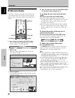
Page 28: ...change the position of the subscreen in picture in picture mode Press the remote control unit s PIP SHIFT button Each time the button is pressed the position of the subscreen moves in the following order To display the currently selected input Press the DISPLAY button If the DISPLAY button is pressed while in multiscreen mode the main screen and sub screen will each be displayed with its currently...

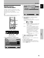
Page 29: ...c signal ON If a sync signal is not detected a warning message is first displayed for 8 seconds after which the display automatically enters the standby mode and the STANDBY ON indicator flashes green If a sync signal is input again later the Plasma Display automatically returns to normal operating mode 1 1 Except when input signal is G ON SYNC or composite SYNC 4 When the setup is finished press ...

Page 30: ...et PICTURE mode settings to the default If settings have been adjusted excessively or the picture on the screen no longer appears natural it may prove more beneficial to reset the PICTURE mode to default settings instead of trying to make adjustments under already adjusted conditions 1 In step 2 in the previous procedure use the 5 buttons to select PICTURE RESET then press the SET button SET SET E...

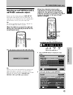
Page 31: ...TO SETUP MODE to INACTIVE and use the manual adjustment methods explained in the following section Adjusting screen POSITION CLOCK and PHASE manual adjust AUTO SET UP When the automatic setup mode is selected the unit will automatically be adjusted to the optimum image settings whenever the power is turned on the input source is changed or the type of input signal is changed MENU 5 SET 2 3 1 Press...

Page 32: ...U button to return to the normal screen image Note Optimum settings may not be possible for low luminance and certain other signals In such cases set the AUTO SETUP MODE to INACTIVE and use the manual adjustment methods explained in the following section Adjusting screen POSITION CLOCK and PHASE manual adjust 3 INACTIVE ACTIVE 2 1 Press the MENU button to display the menu screen SCREEN SETUP OPTIO...

Page 33: ...ker of screen letters or color misalignment This setting adjusts the phase of the internal clock signal adjusted by the CLOCK setting Notes The CLOCK and PHASE adjustment items are supported only for INPUT1 When the CLOCK frequency is changed the POSITION command s horizontal H option may require readjustment If the adjustment items in the SCREEN mode are adjusted excessively the picture may not b...

Page 34: ...ETTING SCREEN MGT SPLIT FREEZE AUTO SETUP MODE AUTO FUNCTION PIP DETECT PICTURE STANDARD INACTIVE OFF ACTIVE ENGLISH OFF 4 Use the 5 buttons to select ORBITER CHANGE SET EXIT MENU SCREEN MANAGEMENT ORBITER SOFT FOCUS OFF OFF 5 Press the SET button to activate the setting The factory default setting is OFF Each time the button is pressed the setting alternates as follows OFF The ORBITER is not bein...

Page 35: ...UP OPTION LANGUAGE ENERGY SAVE TIMER SETTING SCREEN MGT SPLIT FREEZE AUTO SETUP MODE AUTO FUNCTION PIP DETECT PICTURE STANDARD INACTIVE OFF ACTIVE ENGLISH OFF 4 Use the 5 buttons to select SOFT FOCUS CHANGE SET EXIT MENU SCREEN MANAGEMENT ORBITER SOFT FOCUS OFF OFF 5 Press the SET button to activate the setting The factory default setting is OFF Each time the button is pressed the setting alternat...

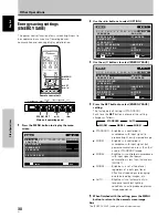
Page 36: ...ACTIVE ENGLISH OFF 4 Press the SET button to select ENERGY SAVE setting The factory default setting is STANDARD Each time the SET button is pressed the setting changes as follows STANDARD Brightness is controlled in accordance with input signal to produce bright easily viewed image MODE1 Brightness is controlled in accordance with input signal but power consumption is less than that used in STANDA...

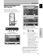
Page 37: ...NCTION is disabled INPUT1 When a signal is detected at INPUT1 the input source automatically switches to INPUT1 After the AUTO FUNCTION mode has caused the input to switch if the input signal is no longer detected the input source reverts to the one selected before operation of the AUTO FUNCTION mode If the input changes when the unit is in AUTO FUNCTION mode pressing the INPUT button to select a ...

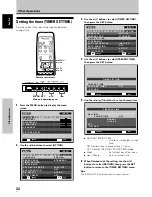
Page 38: ...E Use to set to daylight savings time ON Displays time as present time 1 hour OFF Disables DAYLIGHT SAVING TIME mode Week Set current day of the week Hour Minute Sets to current time 6 When finished with the setting use the 5 buttons to select RETURN then press the SET button to return to the TIMER SETTING menu Note The TIMER SETTING setting affects all input sources MENU 5 SET 2 3 1 Press the MEN...

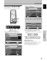
Page 39: ... MGT SPLIT FREEZE AUTO SETUP MODE AUTO FUNCTION PIP DETECT PICTURE STANDARD INACTIVE OFF ACTIVE ENGLISH OFF 4 Use the 5 buttons to select PROGRAM TIMER CHANGE SET EXIT MENU TIMER SETTING PROGRAM TIMER RETURN OFF PRESENT TIME 5 Press the SET button to activate the setting The factory default setting is OFF Each time the button is pressed the setting alternates as follows 6 When finished with the se...

Page 40: ...VE OFF ACTIVE ENGLISH OFF 3 Use the 5 buttons to select PIP DETECT MENU INPUT1 CHANGE SET EXIT MENU SCREEN SETUP OPTION LANGUAGE ENERGY SAVE TIMER SETTING SCREEN MGT SPLIT FREEZE AUTO SETUP MODE AUTO FUNCTION PIP DETECT PICTURE STANDARD INACTIVE OFF ACTIVE ENGLISH OFF 4 Press the SET button to activate the setting The factory default setting is ACTIVE Each time the button is pressed the setting al...

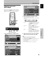
Page 41: ... SET button to activate the setting The factory default setting is OFF Each time the button is pressed the setting alternates as follows OFF The still picture displayed at the time the FREEZE button was pressed is displayed as a single fullscreen image S BY S When the FREEZE button is pressed the freeze frame image will be displayed in the side by side subscreen PIP When the FREEZE button is press...

Page 42: ...kdown or fire Troubleshooting What may at first seem to be an malfunction may be remedied with a quick check Please check to see if a warning is displayed on the screen If displayed refer to the table below and check the mode If there is no display check to see if the problem is listed on page 37 The problem may also be caused by something other than this unit so please also check the other compon...

Page 43: ...e Plasma Display panel Not a malfunction Fan speed changes automatically in accordance with ambient conditions Not a malfunction The ON indicator may not light in some cases depending on the settings performed by the installer Consult with your installation technician Problem Possible Solution No power Unit cannot be operated Remote control does not operate Picture is cut off Strange color light c...

Page 44: ...a malfunction Concerning infrared light In principle the Plasma Display radiates infrared light Depending on the environment in which the monitor is installed and used infrared remote control units for other nearby appliances may fail to operate properly or noise may be heard in wireless headphones In such cases move the affected appliance to a location where its infrared sensor is not affected El...

Page 45: ...sync Compatible with Microsoft Plug Play VESA DDC1 2B Output Mini D sub 15 pin socket connector 75 Ω with buffer Additional Information INPUT2 Input DVI D 24 pin connector Digital RGB signal DVI compliant TMDS signal Compatible with Microsoft Plug Play VESA DDC 2B Audio Input AUDIO INPUT for INPUT1 Stereo mini jack L R 500 mVrms more than 10 kΩ AUDIO INPUT for INPUT2 Stereo mini jack L R 500 mVrms...

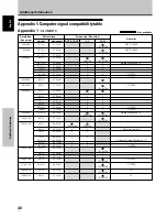
Page 46: ...00 832x624 1360x765 1024x768 1280x768 1360x768 1376x768 1280x800 1280x854 NEC PC 9800 NEC PC 9800 Apple Macintosh 13 I O DATA I O DATA I O DATA I O DATA I O DATA Apple Macintosh 16 Work station SGI indicates Apple Macintosh 19 I O DATA I O DATA I O DATA CVT PC 1024x768 1024x768 1024x768 1024x768 1024x768 1024x768 1024x768 1024x768 1024x768 1024x768 1024x768 1024x768 1024x768 1024x768 31 5kHz 31 5k...

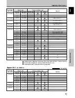
Page 47: ...1024x768 1024x768 1024x768 1024x768 1024x768 1024x768 1024x768 1024x768 1024x768 1024x768 Apple Macintosh 21 Sun Microsystems LO Sun Microsystems HI Apple Macintosh 17 Work station SGI Work station EWS4800 Work station EWS4800 Work station HP Work station SUN I O DATA CVT CVT Optimal picture Adjustment of picture position refresh rate phase etc may be necessary Picture will be enlarged but some fi...

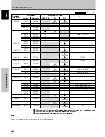
Page 48: ...Hz 60 0kHz 64 0kHz 64 6kHz 75 1kHz 78 1kHz 81 1kHz 80 0kHz 91 2kHz 65 3kHz 65 3kHz 75 0kHz 74 0kHz 1024x768 768x768 768x768 768x768 768x768 768x768 768x768 768x768 768x768 1024x768 1024x768 1024x768 1024x768 1024x768 1024x768 1024x768 1024x768 1024x768 1024x768 1024x768 1024x768 1024x768 1024x768 1024x768 Work station SGI I O DATA I O DATA Work station SUN Work station SUN Apple Macintosh17 Work s...

Page 49: ...ta1 T M D S Data1 3 Shield NC No connection NC No connection 5V Power GND Hot Plug Detect T M D S Data0 T M D S Data0 T M D S Data0 5 Shield NC No connection NC No connection T M D S Clock Shield T M D S Clock T M D S Clock Pin No 5 1 15 11 6 10 Appendix 2 INPUT1 2 pin assignments Appendix 2 1 2 INPUT1 Mini D sub 15 pin female connector pin allocation Input Output 1 2 3 4 5 6 7 8 9 10 11 12 13 14 ...

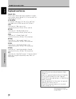
Page 50: ...tes a 1280 dot x 768 line resolution SXGA General term for Super eXtended Graphics Array Generally this indicates a 1280 dot x 1024 line resolution SXGA General term for Super eXtended Graphics Array plus Generally this indicates a 1400 dot x 1050 line resolution DVI General term for Digital Visual Interface An interface standard proposed by the Digital Display Working Group DDWG for digital displ...

Page 51: ...le dans les mois ou les années qui suivent Remarques sur l installation Ce produit est vendu en assumant qu il sera installé par un personnel suffisamment expérimenté et qualifié Faites toujours réaliser le montage et l installation par un spécialiste ou par votre revendeur PIONEER ne peut être tenu responsable pour tout dommage causé par une erreur d installation ou de montage une mauvaise utilis...

Page 52: ...Fr Cet appareil numérique de la classe B est conforme à la norme NMB 003 du Canada Cet appareil a été testé est trouvé conforme avec les limites des appareils numériques de classe B conformément à l article 15 du règlement FCC Ces limites sont conçues pour offrir une protection raisonnable contre les interférences nuisibles dans une installation résidentielle Cet appareil génère utilise et peut ém...

Page 53: ...e lignes électriques aériennes lumières électriques ou autres circuits d alimentation ou dans un endroit où il peut tombé sur une telle ligne électrique ou circuit Lors de l installation d un système d antenne extérieure faites très attention de ne pas toucher de telles lignes électriques ou circuits car un tel contact pourrait entraîner la mort SURCHARGE Ne surchargez pas les prises murales les r...

Page 54: ...Centre de Service Autorisé Pioneer le plus près de chez vous Vous pouvez aussi contacter le Service à la clientèle de Pioneer Pioneer Électroniques du Canada Inc Service à la clientèle 300 Allstate Parkway Markham Ontario L3R OP2 905 479 4411 1 877 283 5901 Pour obtenir des renseignements sur la garantie veuillez vous reporter au feuillet sur la garantie restreinte qui accompagne le produit S021_E...

Page 55: ...ssement partiel de l image POINT ZOOM 21 Affichage multi écran 22 Mise hors tension automatique GESTION D ALIM 23 Réglages de l IMAGE et de l ÉCRAN 24 Réglage de l IMAGE 24 Réglage de la POSITION de l écran de l HORLOGE et de la PHASE Réglage automatique 25 Réglage de la POSITION de l écran de l HORLOGE et de la PHASE Réglage manuel 26 Autres démarches 28 Réglage de l orbiteur ORBITER 28 Réglage d...

Page 56: ...A De plus les réglages de rapport largeur hauteur et de taille d écran supportés comprennent POINT PAR POINT 4 3 et PLEIN ÉCRAN 1 Les signaux pris en compte sont différents à INPUT1 et à INPUT2 1 L aspect du rapport largeur hauteur et de la taille d écran varie selon le signal d entrée Configuration d installation plus libre Possibilités élargies d installation par un solide design plus mince et p...

Page 57: ...0 couvre tous les aspects de l installation de l écran à plasma et des raccordements à effectuer avec les autres appareils de l installation La section Paramètres du système qui débute à la page 16 traite des réglages sur écran nécessaires pour que l écran à plasma fonctionne correctement avec les autres composants raccordés En fonction des raccordements réalisés il peut être utile de lire cette s...

Page 58: ...PUT1 ou INPUT2 et chaque signal Paramètres qui peuvent être réglés IMAGE Voici de brèves explications sur les paramètres qui peuvent être réglés grâce à l option IMAGE CONTRASTE Réglez le contraste en fonction de l éclairage ambiant de manière que l image soit bien visible LUMINOSITÉ Réglez la luminosité de manière que les parties sombres de l image soient bien visibles AGRAND HOR Pour accroître l...

Page 59: ... AA R6 4 Chiffon de nettoyage pour l écran 5 5 colliers rapides 6 2 noyaux en ferrite 7 3 noyaux en ferrite 8 2 supports pour l écran 9 2 rondelles petite 0 2 boulons hexagonaux Support pour télécommande Attaches de câble Le présent mode d emploi Carte de garantie Utilisez ce support pour y ranger la télécommande Si vous fixez ce support à l arrière de l écran veiller à ne pas obstruer les ouïes d...

Page 60: ...ignotement de ce témoin indique la présence de messages d erreur page 38 5 Poignées Panneau de commande de l écran à plasma 6 Touche STANDB ON veille marche Appuyez sur cette touche pour mettre l écran en service ou en veille page 18 7 Touche MENU Appuyez sur cette touche pour ouvrir ou fermer les menus s affichant sur l écran pages 16 à 35 8 Touche DISPLAY SET écran validation Elle sert à valider...

Page 61: ...timales page 25 Touche STANDBY ON Appuyez sur cette touche pour mettre l écran en service ou en veille page 18 Touche DISPLAY Appuyez sur cette touche pour afficher le nom de l entrée et de mode de fonctionnement actuels page 19 Touche POINT ZOOM Utilisez cette touche pour choisir et agrandir une partie de l écran page 21 Touche FREEZE Quand la fonction d écran de mémo est validée une image fixe e...

Page 62: ...élécommande ne soit endommagé par une fuite de l électrolyte des piles retirez en les piles si vous envisagez de ne pas l utiliser pendant un mois environ Si les piles ont fuit nettoyez soigneusement le logement et utilisez un jeu de piles neuves Lorsque vous diposez de piles batteries usées veuillez vous conformer aux normes gouvernementales ou environnementales en vigueur dans votre pays ou régi...

Page 63: ... INPUT1 mini prise D sub à 15 broches Utilisez la prise ANALOG RGB OUT INPUT1 pour appliquer le signal vidéo sur un monite ur extérieur ou un autre appareil Remarque Le signal vidéo n est pas présent sur la prise ANALOG RGB OUT INPUT1 lorsque l écran à plasma est hors tension ou en veille page 12 7 ANALOG RGB IN INPUT1 mini prise D sub à 15 broches Utilisez ces prises pour le branchement d un ordi...

Page 64: ...s séparément Dans toute la mesure du possible utilisez des pièces et des accessoires fabriqués par PIONEER PIONEER ne pourra être tenue responsable des accidents et dommages qui résulteraient de l utilisation de pièces ou d accessoires fabriqués par des tiers Pour effectuer une installation personnalisée consultez le revendeur ou un technicien compétent Accrochage de l écran à plasma à un mur L éc...

Page 65: ...ment de l écran il doit toujours être transporté par deux personnes saisissant les poignées arrière comme illustré ici NON N essayez jamais de déplacer l écran à plasma en ne le tenant que par une de ses poignées Perçage b Appareil Axe Perçage b Perçage b Perçage b Axe Perçage a Perçage b Boulon Boulon Surface de pose Fixation etc 12 à 18 mm 12 à 14 mm Vue arrière Vue de côté Perçage a Perçage a O...

Page 66: ...e revendeur NOTICE La prise INPUT1 prend en compte les composants à approche Plug Play VESA DDC 1 2B de Microsoft Consultez le Supplément 2 1 2 page 43 lors de connexions sur INPUT1 Consultez le Supplément 1 pages 40 à 41 pour des informations sur les signaux et les formats d affichage pris en compte par INPUT1 Installation et raccordements Pour le raccordement à ANALOG RGB OUT INPUT1 ANALOG RGB O...

Page 67: ... cet écran à plasma Cet écran à plasma est doté de deux entrées audio et d une sortie audio Le tableau qui suit donne pour chaque entrée vidéo les entrées audio correspondantes Torsadez les brins mis à nu Soulevez la languette puis introduisez le conducteur Abaissez la languette pour maintenir le conducteur en place Raccordement audio pour un appareil ordinateur relié à INPUT1 AUDIO AUDIO INPUT1 A...

Page 68: ...terre NON Alimentez l écran à plasma à partir de la tension prescrite 100 120 Volts CA 50 60 Hz tout autre tension peut provoquer un incendie ou une secousse électrique 1 2 Noyau en ferrite Attache de câble Cordon d alimentation À la prise secteur Le plus près possible À la prise AC IN Fixation des noyaux en ferrite Pour éviter des parasites fixez les noyaux en ferrite fournis comme accessoires su...

Page 69: ...as ma puis insérez 2 à l arrière de 1 pour assurer la fixation Les colliers rapides sont conçus pour que l ouverture soit difficile Fermez les soigneusement Fixation des colliers rapides à l écran à plasma Utilisez les trous indiqués par le signe selon les besoins Pour retirer les colliers rapides A l aide d une pince tordez le collier de 90 puis tirez le vers vous Avec le temps le collier peut se...

Page 70: ...TIMER SETTING SCREEN MGT SPLIT FREEZE AUTO SETUP MODE AUTO FUNCTION PIP DETECT PICTURE STANDARD INACTIVE OFF ACTIVE ENGLISH OFF 5 Utilisez les touches 5 pour sélectionner LANGUAGE puis appuyez sur la touche SET LANGUAGE ENGLISH SET SET EXIT MENU 6 Utilisez les touches 2 3 pour sélectionner la langue souhaitée A chaque pression sur les touches 2 3 les langues disponibles changent dans l ordre suiva...

Page 71: ...ignal d entrée VALIDER SET SORTIE MENU TYPE DE SIGNAL AUTO A chaque pression sur les boutons 2 3 la sélection alterne comme suit AUTO Les signaux sont automatiquement détectés en accord avec le tableau des comptabilités de signal d ordinateur pages 40 à 42 Autres Les résolutions utilisables sont affichées 5 Appuyez sur la touche SET Le réglage est mémorisé et l écran repasse à celui illustré à l é...

Page 72: ...affiché POL H POL V PLEIN ÉCRAN SIGNAL NON RECONNU FH 86 7kHz ATTENTION FV 88 5Hz ENTRÉE1 4 Utilisez les touches VOLUME pour ajuster le volume sonore Si aucune signal sonore n est appliqué à l écran à plasma cette opération est inutile 5 Lorsque vous avez fini de regarder les images appuyez sur la touche STANDBY ON pour placer l écran à plasma en veille 6 Réglez l interrupteur MAIN POWER du pannea...

Page 73: ...arque Il se peut que les fréquences de rafraîchissement affichées soient légèrement différentes des valeurs réelles STANDBY ON MENU DISPLAY SET VOL INPUT SCREEN SIZE VOL VOLUME Télécommande Panneau de commande de l écran à plasma MUTING STANDBY ON MENU DISPLAY SET VOL INPUT SCREEN SIZE DISPLAY SET DISPLAY Panneau de commande de l écran à plasma Télécommande Appuyez sur la touche MUTING de la téléc...

Page 74: ...nal d entrée original A 2 4 3 L image remplit l écran autant que possible mais le format n est pas modifi A 3 PLEIN ÉCRAN L image a le format 16 9 et remplit l écran A Le format d image change comme suit chaque fois que la touche SCREEN SIZE est actionnée ou Consultez le Tableau des compatibilités de signal d ordinateur pages 40 à 42 pour des renseignements sur les tailles d écran supportées par c...

Page 75: ...Si le signal d entrée change si la page de menu est affichée et que l entrée est changée ou si le mode multi écran est sélectionné la fonction Agrandissement partiel de l image POINT ZOOM sera annulée Fonctionnement Agrandissement partiel de l image POINT ZOOM Cet écran à plasma autorise un agrandissement de l image affichée Lorsque l image est agrandie la zone de sa vision peut être déplacée sur ...

Page 76: ...ommande À chaque pression sur cette touche la position du sous écran change dans l ordre suivant Pour afficher l entrée actuellement sélectionnée Appuyez sur la touche DISPLAY Si la touche DISPLAY est actionnée en mode Multi écran l écran principal et le sous écran afficheront respectivement leur entrée actuellement sélectionnée Remarques Lorsque l écran à plasma est utilisé pour une activité à bu...

Page 77: ...r quitter la page de menu Remarque La fonction GESTION D ALIM doit être réglée individuellement pour chaque entrée INPUT1 et INPUT2 Pour revenir au mode de fonctionnement Pour repasser au mode de fonctionnement normal depuis le mode Veille de la fonction GESTION D ALIM faites fonctionner votre ordinateur ou appuyez sur la touche INPUT Fonctionnement 3 ARRÊT MARCHE 2 Mise hors tension automatique G...

Page 78: ... l image dans le sens vertical Pour rétablir les valeurs par défaut des paramètres de l option IMAGE Si les réglages effectués ne vous conviennent pas il peut être souhaitable de rétablir les valeurs par défaut des différents paramètres de l option IMAGE plutôt que de continuer à modifier les réglages 1 Au cours de l opération 2 ci dessus utilisez les touches 5 pour choisir l option RÉINIT IMAGE p...

Page 79: ...rtains autres types Dans ces cas réglez le mode RÉGLAGE AUTO sur INACTIF et utilisez les méthodes de réglage manuel expliquées dans la section suivante Réglage de la POSITION de l écran de l HORLOGE et de la PHASE Réglage manuel Lorsque le mode de paramétrage automatique est sélectionné l appareil sera automatiquement ajusté aux paramètres idéaux lors de sa mise sous tension lorsque la source d en...

Page 80: ...r à l image de l écran normal Remarque Il se peut que les réglages optimaux ne soient pas obtenus avec des signaux à faible luminance ou certains autres types Dans ces cas réglez le mode RÉGLAGE AUTO sur INACTIF et utilisez les méthodes de réglage manuel expliquées dans la section suivante Réglage de la POSITION de l écran de l HORLOGE et de la PHASE Réglage manuel 3 INACTIF ACTIF 2 1 Appuyez sur ...

Page 81: ... scintillement et des erreurs de couleur Ce réglage agit sur la phase du signal de l horloge interne dont la fréquence a été réglée au moyen du paramètre HORLOGE Remarques Les paramètres de réglage HORLOGE et PHASE sont pris en compte uniquement pour ENTRÉE1 Si la fréquence HORLOGE est changée il se peut que l option H de la commande POSITION doive être retouchée Si les paramètres de l option ÉCRA...

Page 82: ...MENU ENTRÉE1 ENTRÉE SORTIE LANGUAGE TIMER MODE AUTO ÉCON ÉNERGIE PROTECT ÉCRAN GEL MULTI IMAGE RÉGLAGE AUTO DÉTECTION PIP 4 Utilisez les touches 5 pour sélectionner ORBITER CHANGER SET SORTIE MENU ANTI MARQUAGE ÉCRAN ORBITER FOCUS LEGER ARRÊT ARRÊT 5 Appuyez sur la touche SET pour valider le réglage Le réglage par défaut effectué en usine est ARRÊT À chaque pression sur la touche le réglage change...

Page 83: ... ARRÊT ÉCRAN SETUP OPTION IMAGE MENU ENTRÉE1 ENTRÉE SORTIE LANGUAGE TIMER MODE AUTO ÉCON ÉNERGIE PROTECT ÉCRAN GEL MULTI IMAGE RÉGLAGE AUTO DÉTECTION PIP 4 Utilisez les touches 5 pour sélectionner FOCUS LEGER SET MENU CHANGER SORTIE ANTI MARQUAGE ÉCRAN ORBITER FOCUS LEGER ARRÊT ARRÊT 5 Appuyez sur la touche SET pour valider le réglage Le réglage par défaut effectué en usine est ARRÊT À chaque pres...

Page 84: ... l option ÉCON ÉNERGIE Le réglage par défaut effectué en usine est STANDARD Le réglage change comme suit chaque fois que la touche SET est actionnée STANDARD La luminosité est ajustée en fonction du signal d entrée afin de produire des images claires et agréables à regarder MODE1 La luminosité est ajustée en fonction du signal d entrée mais la consommation de courant est inférieure à celle du mode...

Page 85: ...RÊT hors service A chaque pression sur la touche SET la fonction du sélecteur permute comme suit ARRÊT Le paramètre MODE AUTO est désactivé ENTRÉE1 Lorsqu un signal est détecté à INPUT1 ENTRÉE1 la source d entrée passe automatiquement à ENTRÉE1 Après que la fonction MODE AUTO a provoqué le changement de l entrée la source d entrée repassera à celle qui était sélectionnée avant l action de la fonct...

Page 86: ... MENU ENTRÉE1 ENTRÉE SORTIE ÉCON ÉNERGIE PROTECT ÉCRAN GEL MULTI IMAGE RÉGLAGE AUTO DÉTECTION PIP 4 Utilisez les touches 5 pour sélectionner HORLOGE puis appuyez sur la touche SET ENTRÉE SET SORTIE MENU TIMER REGLAGE HEURE RETOUR ARRÊT HORLOGE 5 Utilisez les touches 2 3 5 pour ajuster chaque rubrique du menu CHANGER SET SORTIE MENU LUNDI 12 00 00 REGLAGE RETOUR HORLOGE ARRÊT HEURE D ÉTÉ HEURE D ÉT...

Page 87: ...IE ÉCON ÉNERGIE PROTECT ÉCRAN GEL MULTI IMAGE RÉGLAGE AUTO DÉTECTION PIP 4 Utilisez les touches 5 pour sélectionner REGLAGE HEURE SET MENU CHANGER SORTIE TIMER REGLAGE HEURE RETOUR ARRÊT HORLOGE 5 Appuyez sur la touche SET pour valider le réglage Le réglage par défaut effectué en usine est ARRÊT À chaque pression sur la touche le réglage change comme suit 6 Quand les réglages sont terminés utilise...

Page 88: ...ON IMAGE MENU ENTRÉE1 ENTRÉE SORTIE 3 Utilisez les touches 5 pour sélectionner DÉTECTION PIP SET MENU LANGUAGE TIMER MODE AUTO STANDARD INACTIF ARRÊT ACTIF FRANÇAIS ARRÊT ÉCRAN SETUP OPTION IMAGE MENU ENTRÉE1 CHANGER SORTIE ÉCON ÉNERGIE PROTECT ÉCRAN GEL MULTI IMAGE RÉGLAGE AUTO DÉTECTION PIP 4 Appuyez sur la touche SET pour valider le réglage Le réglage par défaut effectué en usine est ACTIF À ch...

Page 89: ...pour valider le réglage Le réglage par défaut effectué en usine est ARRÊT À chaque pression sur la touche le réglage change comme suit ARRÊT L image fixe affichée au moment où la touche FREEZE a été actionné est affichée comme image simple sur la totalité de l écran S BY S Quand la touche FREEZE est actionnée une image gelée est affichée sur le sous écran Côte à côte PIP Quand la touche FREEZE est...

Page 90: ...s être interprétée comme une anomalie de fonctionnement Si une indication est affichée sur l écran consultez le tableau ci dessous Dans le cas contraire et si vous pensez que cet appareil est défectueux procédez aux vérifications de la page 37 Il peut arriver aussi que le défaut provienne d un autre élément de l installation assurez vous que ce n est pas le cas Si en dépit de ces contrôles vous n ...

Page 91: ...IMAGE sont ils corrects page 24 Anomalies Remèdes possibles Anomalies générales Anomalies qui n en sont pas L image a un format réduit Les caractères affichés sont déformés Un son aigu est parfois émis par l écran à plasma Les portions lumineuses de l image semblent manquer d intensité Les taches ou du bruit se forment sur l écran Des rayures se forment sur l écran L écran à plasma émet des bruits...

Page 92: ... et consultez votre revendeur ou un centre de service En outre si l alimentation se coupe d elle même si l appareil ne peut pas être mis sous tension ou si ce témoin clignote en rouge il peut s agir d un dysfonctionnement Débranchez immédiatement la fiche du cordon d alimentation et consultez votre revendeur ou un centre de service Informations complémentaires Précautions relatives à l utilisation...

Page 93: ...2B Sortie Mini D sub 15 broches connecteur femelle 75 Ohms avec tampon INPUT2 Entrée Connecteur DVI D à 24 broche Signal RVB numérique DVI conforme au signal TMDS Compatibilité Microsoft Plug Play VESA DDC 2B Audio Entrée Entrée audio pour INPUT1 Mini prise stéréo G D 500 mV eff plus de 10 kOhms Entrée audio pour INPUT2 Mini prise stéréo G D 500 mV eff plus de 10 kOhms Sortie Sortie audio Mini fic...

Page 94: ... I O DATA I O DATA CVT PC 1024x768 1024x768 1024x768 1024x768 1024x768 1024x768 1024x768 1024x768 1024x768 1024x768 1024x768 1024x768 1024x768 1024x768 31 5kHz 31 5kHz 37 9kHz 31 5kHz 35 0kHz 37 9kHz 37 5kHz 43 3kHz 51 1kHz 61 3kHz 31 0kHz 31 7kHz 35 2kHz 37 9kHz 48 1kHz 46 9kHz 53 7kHz 63 0kHz 75 7kHz 49 7kHz 47 7kHz 48 4kHz 49 7kHz 56 5kHz 60 0kHz 60 2kHz 68 7kHz 80 5kHz 45 1kHz 47 8kHz 56 1kHz ...

Page 95: ... 768x768 768x768 768x768 1024x768 1024x768 1024x768 1024x768 1024x768 1024x768 1024x768 1024x768 1024x768 1024x768 1024x768 Apple Macintosh 21 Sun Microsystems LO Sun Microsystems HI Apple Macintosh 17 Station de travail SGI Station de travail EWS4800 Station de travail EWS4800 Station de travail HP Station de travail SUN I O DATA CVT CVT Informations complémentaires Définition Points x Lignes Ver...

Page 96: ... 1024x768 1024x768 1024x768 1024x768 1024x768 1024x768 1024x768 Station de travail SGI I O DATA I O DATA Station de travail SUN Station de travail SUN Apple Macintosh17 Station de travail SGI Station de travail EWS4800 Station de travail EWS4800 Station de travail HP Station de travail SUN CVT Informations complémentaires Définition Points x Lignes Vertical POINT PAR POINT PLEIN ÉCRAN Remarques Fo...

Page 97: ...broche 5 1 15 11 6 10 Supplément 2 2 2 Bornage de INPUT2 connecteur femelle DVI 1 8 24 17 9 16 Affectation des signaux 1 2 3 4 5 6 7 8 9 10 11 12 13 14 15 16 17 18 19 20 21 22 23 24 T M D S Donnée 2 T M D S Donnée 2 T M D S Blindage Donnée 2 4 Réservé pas de connexion Réservé pas de connexion Horloge DDC Donnée DDC Réservé pas de connexion T M D S Donnée 1 T M D S Donnée 1 T M D S Blindage Donnée ...

Page 98: ...finition WXGA est de 1280 points x 768 lignes SXGA SXGA est l abréviation de Super eXtended Graphics Array En général la définition SXGA est de 1280 points x 1024 lignes SXGA SXGA est l abréviation de Super eXtended Graphics Array plus En général la définition SXGA est de 1400 points x 1050 lignes DVI DVI est l abréviation de Digital Visual Interface Interface visuelle numérique C est l interface ...

Reviews: