background image

 19

RS-232C Adjustment

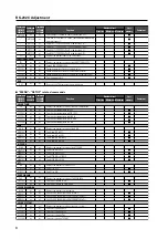
Sequence

Data Content

Size

Remarks

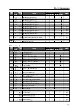
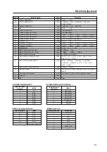
27

PRO USE UNDERSCAN

1 Byte

0: OFF

1: ON

28

PRO USE IMAGE PROCESS

1 Byte

1: NORMAL 2: PURE 3: MONOTONE 4: BLUE ONLY

5: HIGH CONTRAST

29

PRO USE SYGNAL TYPE

1 Byte

1: MOTION 2: STILL 3: NONE STD

30

FRC

1 Byte

0: OFF

1: ON

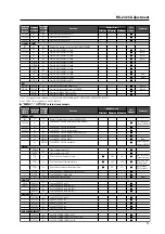
31

POWER ON MODE INPUT

1 Byte

See the table below.

32

POWER ON MODE MULTI MODE

1 Byte

See the table below.

33

POWER ON MODE MULTI INPUT 1

1 Byte

1: INPUT

2: INPUT2

3: INPUT3

4: INPUT4

5: INPUT5

34

POWER ON MODE MULTI INPUT 2

1 Byte

1: INPUT

2: INPUT2

3: INPUT3

4: INPUT4

5: INPUT5

35

POWER ON MODE VOLUME

2 Byte

0 to 42: In the case of last memory, FF

36

SEAMLESS SW

1 Byte

0: OFF

1: ON

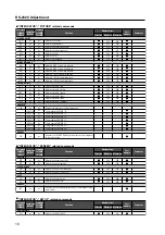
37

SEAMLESS SW SELECT1

1: INPUT

2: INPUT2

3: INPUT3

4: INPUT4

5: INPUT5

38

SEAMLESS SW SELECT2

1 Byte

1: INPUT

2: INPUT2

3: INPUT3

4: INPUT4

5: INPUT5

39

MIRROR MODE

1 Byte

0: OFF

1: X

2: Y

3: XY

40

MULTI SCREEN SET (S BY S SIZE)

1 Byte

1: NORMAL

2: FULL

41

MULTI SCREEN SET (S BY S LAYOUT)

1 Byte

1: MODE1

2: MODE2

3: MODE3

42

MULTI SCREEN SET (PIP SIZE)

1 Byte

1: 1 (SMALL) to 4: 4 (LARGE)

43

MULTI SCREEN SET (TRANSLUCENT)

1 Byte

0: OFF

1: 10 %

2: 20 %

3: 30 %

4: 40 %

5: 50 %

6: 60 % 7: 70 %

8: 80 %

44

MULTI SCREEN SET (BANNER PIP)

1 Byte

0: OFF

1: BOTTOM1

2: BOTTOM2

3: BOTTOM3

4: MID LOW

5: MID HIGH

6: TOP3

7: TOP2

8: TOP1

9: LEFT A: RIGHT

45

MULTI SCREEN SET (BANNER INPUT)

1 Byte

1: INPUT1

2: INPUT2

46

Main input function

3 Byte

Input functions of the main screen (refer to the following table for

details)

47

Main screen size information

1 Byte

Main screen size (refer to the following table for details)

48

Check sum

2 Byte

49

ETX

1 Byte

03hex

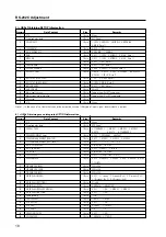
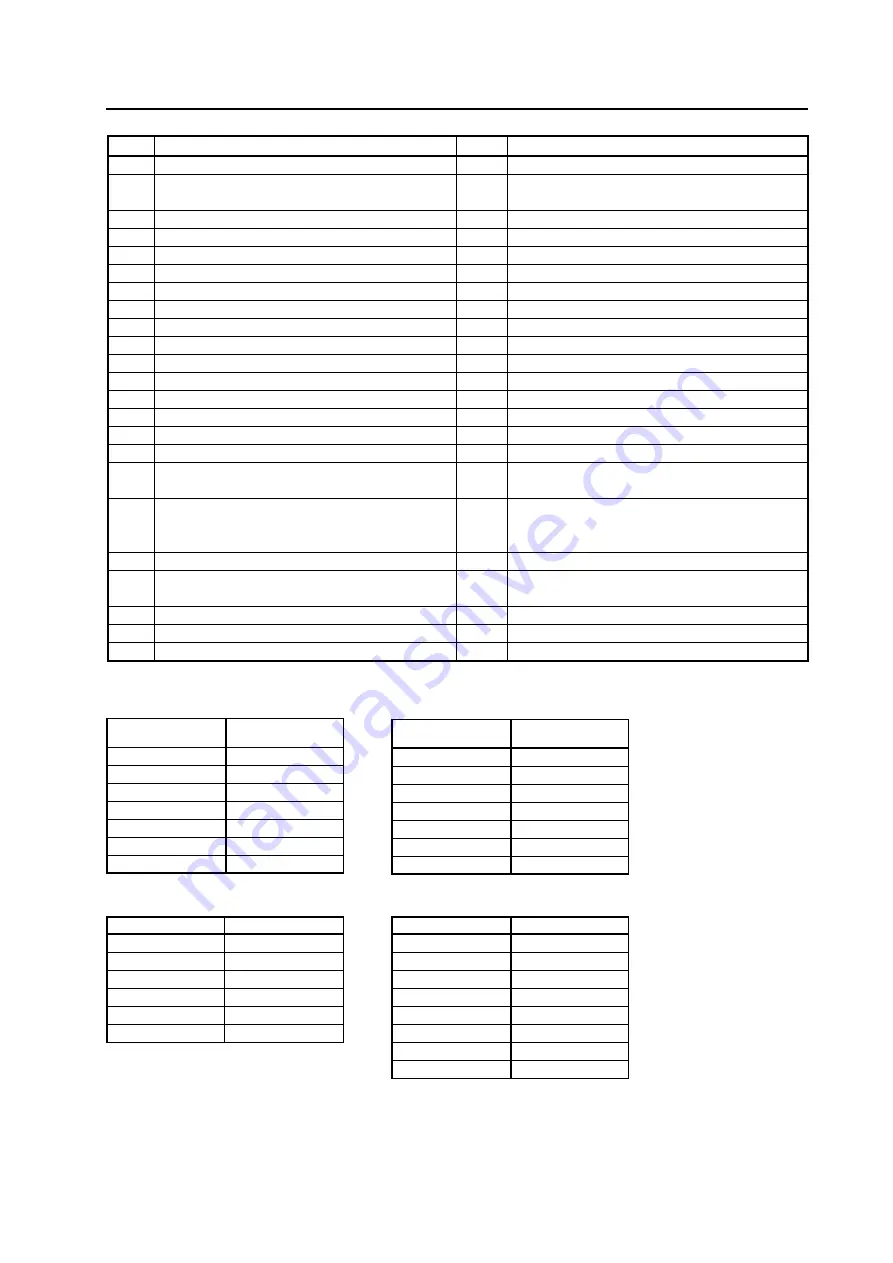
Input functions

INPUT

(response)

1

SIDE BY SIDE1

2

SIDE BY SIDE2

3

SIDE BY SIDE3

4

BOTTOM LEFT

5

BOTTOM RIGHT

6

TOP RIGHT

7

TOP LEFT

Input functions

INPUT

(response)

0

LAST

1

INPUT1

2

INPUT2

3

INPUT3

4

INPUT4

5

INPUT5

A

MULTI

Input function

Input

IN1

INPUT1

IN2

INPUT2

IN3

INPUT3

IN4

INPUT4

IN5

INPUT5

* * *

Unconfirmed (standby time)

7

 POWER ON MODE INPUT

7

 POWER ON MODE MULTI MODE

7

 Main screen input function

Main screen size

Screen size

0

 DOT BY DOT

1

4 : 3

2

FULL

3

ZOOM

5

WIDE

6

14 : 9

9

UNDER SCAN

A

2.35 : 1

7

 Main screen size

Summary of Contents for PureVision PDP-427CMX

Page 1: ...formation for controlling the PDP 427CMX industrial plasma display panel with an external communication device by using serial commands Released January 23 2007 TABLE OF CONTENTS 1 About the RS 232C Adjustment 2 2 Interface 3 3 Combination Connection 4 4 ID Assignment 5 5 List of Commands 7 6 QUEST Commands 15 ...

Page 2: ...ry and some that are not For details refer to section 5 5 5 List of RS 232C Commands pg 267 Also when storing values in last memory the conditions described in section 5 1 5 Last Memory pg 170 must be satisfied 3 OSDS00 OSDS01 OSD display disable enable setting Regardless of the setting the following items can be displayed Menu display menu mode integrator mode Warnings before Auto Power OFF or Po...

Page 3: ... not connected 2 TxD Transmit Data 3 RxD Receive Data 4 NC not connected 5 GND Pin No Signal 6 NC not connected 7 NC not connected 8 RTS Request To Send 9 NC not connected 1 Sending one command at a time STX 02 hex ID 2 Byte COMMAND 3 Byte or 6 Byte ETX 03 hex 2 Sending numerical direct commands STX 02 hex ID 2 Byte COMMAND 3 Byte ARGUMENT 3 Byte ETX 03 hex ID COMMAND ARGUMENT are transmitted as A...

Page 4: ...al can be used at the same time Connecting them at the same time could cause errors Also do not pair combination IN terminals or combination OUT terminals Doing so could cause communication to fail It is possible to use a general purpose mini DIN 6 pin straight cable for the combination cable Note To output RS 232C signals from the combination OUT terminal an ID must be assigned For details refer ...

Page 5: ...IDC Clear the IDs assigned for all panels 2 IN1 The input for which the first digit is 2 is set to INPUT1 Precautions when assigning IDs Panels connected after a display s ID has been cleared cannot be operated with RS 232C commands When the IDC command is sent the IDs for all the sets from Set 1 to Set 4 are cleared Only the first panel which is directly connected to the PC can be controlled Send...

Page 6: ...or linking cable Mini Din 6 pin straight 7 strand cable For one strand suitable for AWG28 Cross section area 0 08 mm2 7 strands π r2 7 3 14 0 062 0 079 mm2 0 08 mm2 Note For details on the number of displays that can be connected in series using the video OUT terminal INPUT1 4 refer to section 2 3 Controls and Connectors pg 12 PC RS 232C Combination cable 5m Plasma Display 1 2 3 OUT IN OUT IN OUT ...

Page 7: ... input to the full screen SWS Outputs sub input to the full screen SCREEN SIZE AST Executes auto setup SZM Displays the present screen size SZMS00 Sets SCREEN SIZE to DOT BY DOT SZMS01 Sets SCREEN SIZE to 4 3 SZMS02 Sets SCREEN SIZE to FULL SZMS03 Sets SCREEN SIZE to ZOOM SZMS05 Sets SCREEN SIZE to WIDE SZMS06 Sets SCREEN SIZE to 14 9 SZMS09 Sets SCREEN SIZE to UNDERSCAN SZMS10 Sets SCREEN SIZE to...

Page 8: ...aximum COLOR TEMP CTP Displays the present set value of the color temperature CTPS01 Sets the color temperature to LOW CTPS02 Sets the color temperature to MID LOW CTPS03 Sets the color temperature to MIDDLE CTPS04 Sets the color temperature to MID HIGH CTPS05 Sets the color temperature to HIGH DNR DNR Displays the present set value of the DNR DNRS00 Sets digital NR to OFF DNRS01 Sets digital NR t...

Page 9: ...mmand 427CMX 507CMX Function Number direct Last memory Comment Effective Minimum Maximum ENERGY SAVE ESV Displays the present set value of ENERGY SAVE ESVS00 Sets ENERGY SAVE to STANDARD STANDARD1 Sets STANDARD1 only on the 507CMX ESVS01 Sets ENERGY SAVE to save energy ESVS02 Sets ENERGY SAVE to fixed brightness ESVS03 Sets ENERGY SAVE to mode 3 long service life ESVS04 Sets ENERGY SAVE to AUTO ES...

Page 10: ...0 CGM Adjusts color detail magenta 000 060 GAMMA GRA Displays the present set value of gradation GRAS18 Sets gradation GAMMA 1 8 GRAS19 Sets gradation GAMMA 1 9 GRAS20 Sets gradation GAMMA 2 0 GRAS21 Sets gradation GAMMA 2 1 GRAS22 Sets gradation GAMMA 2 2 GRAS23 Sets gradation GAMMA 2 3 GRAS24 Sets gradation GAMMA 2 4 PRESET STD Restores the PICTURE W B adjustment value of the integrator to the i...

Page 11: ...ing DIVIDER 2 x 2 not accounting for joints nn 05 to 08 Sets display position during DIVIDER 2 x 2 accounting for joints nn 10 to 18 Sets display position during DIVIDER 3 x 3 not accounting for joints nn 20 to 28 Sets display position during DIVIDER 3 x 3 accounting for joints nn 30 to 3F Sets display position during DIVIDER 4 x 4 not accounting for joints nn 40 to 4F Sets display position during...

Page 12: ...he present set value of FRC FRCS00 Sets the FRC to OFF FRCS01 Sets the FRC to ON Note 1 SEAMLESS INPUT SWITCH SLSS00 Sets the SEAMLESS INPUT SWITCH mode to OFF SLSS01 Sets the SEAMLESS INPUT SWITCH mode to ON SL1S01 Sets the SEAMLESS SW SELECT 1 to INPUT1 SL1S02 Sets the SEAMLESS SW SELECT 1 to INPUT2 SL1S03 Sets the SEAMLESS SW SELECT 1 to INPUT3 SL1S04 Sets the SEAMLESS SW SELECT 1 to INPUT4 SL1...

Page 13: ...mment Effective Minimum Maximum DISPLAY CALL DITS01 Displays DISPLAY CALL 1 DITS02 Displays DISPLAY CALL 2 IM0 INFORMATION write in 1 3 characters IM1 INFORMATION write in 4 6 characters IM2 INFORMATION write in 7 9 characters IM3 INFORMATION write in 10 12 characters IM4 INFORMATION write in 13 15 characters IM5 INFORMATION write in 16 18 characters IM6 INFORMATION write in 19 21 characters IMD C...

Page 14: ...w RMCS28 Remote control key CLEAR New RMCS29 Remote control key FREEZE New RMCS30 Remote control key STANDBY ON New RMCS31 Remote control key VOLUME UP New RMCS32 Remote control key VOLUME DOWN New RMCS33 Remote control key MUTING New RMCS34 Remote control key SCREEN SIZE New RMCS35 Remote control key SPLIT New RMCS36 Remote control key SUB INPUT New RMCS37 Remote control key PIP SHIFT New RS 232C...

Page 15: ... command 7 Quest Command Table STX 02hex Command 3 Byte Data Data ETX 03hex Checksum 2 Byte RS 232C Adjustment Command 434CMX 505CMX Command 425CMX Command 427CMX 507CMX Function Number direct Last memory Comment Effective Minimum Maximum GST QST Obtains status information GPI QPI Obtains integrator PICTURE information GWB QWB Obtains integrator WHITE BALANCE information GPS QPS Obtains integrator...

Page 16: ...2 FULL 3 ZOOM 5 WIDE 6 14 9 9 UNDERSCAN A 2 35 1 12 Two screen display state 1 Byte 0 OFF 1 screen 1 SIDE BY SIDE 1 2 PinP lower right 3 PinP upper right 4 PinP upper left 5 PinP lower left 6 SIDE BY SIDE 2 L 9 SIDE BY SIDE 2 R A SIDE BY SIDE 3 B SIDE BY SIDE 4 L C SIDE BY SIDE 4 R 13 Functional lock information 1 Byte 0 LOCK OFF 1 BUTTONS LOCK 2 IR LOCK 2 IR LOCK 3 IR BUTTONS LOCK 4 MEMORY LOCK 1...

Page 17: ...ummy data is output 3 QWB Obtaining integrator WHITE BALANCE information Sequence Data Content Size Remarks 1 STX 1 Byte 02hex 2 Command echo back 3 Byte QWB fixed 3 R HIGH 3 Byte 000 to 255 Note 1 4 G HIGH 3 Byte 000 to 255 Note 1 5 B HIGH 3 Byte 000 to 255 Note 1 6 R LOW 3 Byte 000 to 255 Note 1 7 G LOW 3 Byte 000 to 255 Note 1 8 B LOW 3 Byte 000 to 255 Note 1 9 Main input function 3 Byte Same a...

Page 18: ... OPTION information Sequence Data Content Size Remarks 1 STX 1 Byte 02hex 2 Command echo back 3 Byte QSO fixed 3 ENERGY SAVE 1 Byte 0 STANDARD1 1 MODE1 2 MODE2 3 MODE3 4 AUTO 5 MUTE 6 STANDARD2 4 PROGRAM REPEAT timer 1 Byte 0 OFF 1 PROGRAM 2 REPEAT 5 SCREEN MANAGEMENT ORBITER 1 Byte 0 OFF 1 MODE1 2 MODE2 3 MODE3 6 SCREEN MANAGEMENT SOFT FOCUS 1 Byte 0 OFF 1 1 2 2 3 3 4 4 7 AUTO SETUP MODE 1 Byte 0...

Page 19: ...1 MODE1 2 MODE2 3 MODE3 42 MULTI SCREEN SET PIP SIZE 1 Byte 1 1 SMALL to 4 4 LARGE 43 MULTI SCREEN SET TRANSLUCENT 1 Byte 0 OFF 1 10 2 20 3 30 4 40 5 50 6 60 7 70 8 80 44 MULTI SCREEN SET BANNER PIP 1 Byte 0 OFF 1 BOTTOM1 2 BOTTOM2 3 BOTTOM3 4 MID LOW 5 MID HIGH 6 TOP3 7 TOP2 8 TOP1 9 LEFT A RIGHT 45 MULTI SCREEN SET BANNER INPUT 1 Byte 1 INPUT1 2 INPUT2 46 Main input function 3 Byte Input functio...

Page 20: ... Audio mute status 1 Byte 0 OFF 1 ON 5 INPUT1 sub volume 3 Byte 000 to 020 6 INPUT2 sub volume 3 Byte 000 to 020 7 INPUT3 sub volume 3 Byte 000 to 020 8 INPUT4 sub volume 3 Byte 000 to 020 9 INPUT5 sub volume 3 Byte 000 to 020 10 Check sum 2 Byte 11 ETX 1 Byte 03hex 8 QCI Obtaining time information Sequence Data Content Size Remarks 1 STX 1 Byte 02hex 2 Command echo back 3 Byte QCI fixed 3 Time in...

Page 21: ...s loudness LNY Permits loudness MCN Turns off MASK CONTROL MCY Turns on MASK CONTROL MGFS01 Turns on VIDEO WALL MSCS01 Turns on MULTI SCREEN SIM Displays present setting of SIDE MASK SIMS01 Sets setting of SIDE MASK to normal SIMS02 Sets setting of SIDE MASK to overlay 1 SIMS03 Sets setting of SIDE MASK to overlay 2 SZMS04 Sets screen size to CINEMA SZMS08 Sets screen size to FULL 1035i MIR Displa...

Page 22: ...k sum applications Example 1 When the data is missing 1 Byte 47 41 31 30 30 32 38 Here the check sum OB hex and the calculated 3C hex do not match Data 100 missing data 28 Check sum 0B ETX 03 hex STX 02 hex QUEST command QAA The data group is calculated according to rules by a PC application and when these values are added the result is 1C4 hex A value xx where xx is 3C hex is added to 1C4 such th...

Reviews: