DEH-P40MP/XU/EW5
51
5
6
7
8
5
6
7
8
C
D
F
A
B
E
7. GENERAL INFORMATION
7.1 DIAGNOSIS
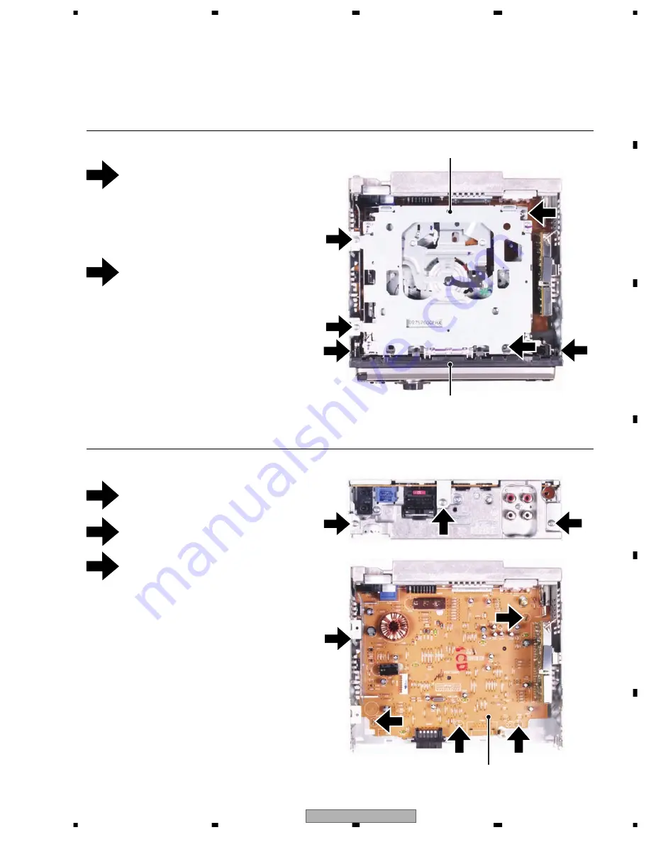
7.1.1 DISASSEMBLY
1
1
2
3
Fig.1
Fig.2
-
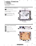
Removing the CD Mechanism Module (Fig.1)
CD Mechanism Module
-
Removing the Grille Assy (Fig.1)
-
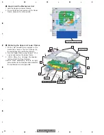
Removing the Tuner Amp Unit (Fig.2)
Grille Assy
Remove the four screws.
1. Remove the Case.
Remove the screw.
Remove the three screws.
Straighten the tabs at four locations
indicated and then remove the Tuner
Amp Unit.
2
1
2
1
2
1
1
2
3
1
3
3
3
2
Disconnect the connector and then remove the
CD Mechanism Module.
Tuner Amp Unit
2
Release the two latchs and then
remove the Grille Assy.
-
Removing the Case (not shown)
Summary of Contents for RDS DEH-P40MP
Page 6: ...DEH P40MP XU EW5 6 1 2 3 4 1 2 3 4 C D F A B E 1 SPECIFICATIONS ...
Page 7: ...DEH P40MP XU EW5 7 5 6 7 8 5 6 7 8 C D F A B E ...
Page 12: ...DEH P40MP XU EW5 12 1 2 3 4 1 2 3 4 C D F A B E 2 3 CD MECHANISM MODULE ...
Page 22: ...DEH P40MP XU EW5 22 1 2 3 4 1 2 3 4 C D F A B E 3 3 KEYBOARD UNIT B LCD DRIVER KEY CONTROLLER ...
Page 23: ...DEH P40MP XU EW5 23 5 6 7 8 5 6 7 8 C D F A B E B A CN804 B KEYBOARD UNIT ...
Page 27: ...DEH P40MP XU EW5 27 5 6 7 8 5 6 7 8 C D F A B E C a C b C b 2 3 A CN701 6 ...
Page 35: ...DEH P40MP XU EW5 35 5 6 7 8 5 6 7 8 C D F A B E A SIDE B PCL ...
Page 37: ...DEH P40MP XU EW5 37 5 6 7 8 5 6 7 8 C D F A B E ...
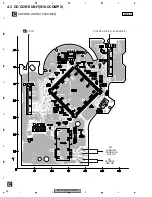
Page 39: ...DEH P40MP XU EW5 39 5 6 7 8 5 6 7 8 C D F A B E C SIDE B C CD CORE UNIT S10 5COMP2 ...
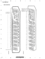
Page 64: ...DEH P40MP XU EW5 64 1 2 3 4 1 2 3 4 C D F A B E 7 2 2 DISPLAY LCD YAW5064 SEGMENT COMMON ...
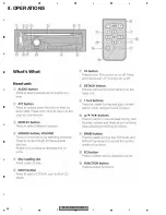
Page 66: ...DEH P40MP XU EW5 66 1 2 3 4 1 2 3 4 C D F A B E 8 OPERATIONS ...
Page 67: ...DEH P40MP XU EW5 67 5 6 7 8 5 6 7 8 C D F A B E CBA1994 ...
Page 68: ...DEH P40MP XU EW5 68 1 2 3 4 1 2 3 4 C D F A B E Connection Diagram ...
Page 69: ...DEH P40MP XU EW5 69 5 6 7 8 5 6 7 8 C D F A B E ...


