RS-P90/EW5
64
1
2
3
4
1
2
3
4
C
D
F
A
B
E
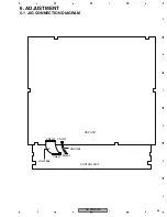
6.2 MASTER CLOCK ADJUSTMENT
(The measuring points for adjusting master clock)
TP3005 or its equivalent land and TP3002 or its equivalent GND
(Waveform Confirmation for Adjustment)
Waveform confirmation is required since the waveform may be deformed according to the
type of probe to be used when adjusting master clock.
The waveform is basically a rectangular wave of 0 --- 3.3 V (24.576 MHz).
(Adjustment Requirements)
Operate the product in the following requirements and make adjustment within 3 or 4 minutes from the start of
such operation.
(Measuring instruments to be used)
Frequency counter or high-frequency probe
-
Master clock adjustment
The adjustment for service should be served in the product condition, instead of in the unit condition.
(Otherwise, it would require jigs.)
Remove the top case, front panel and the shield case of the DSP unit so that the A side of the DSP unit is
visible to adjust.
Adjustment is done by using the trimmer capacitor:
For adjusting master clock --- TC3001
Item
No.
Requirements
Master clock
1
Set volume value of Main Unit to - 72 dB and
reproduce CD without recording.
Rated Value
24.576 MHz 20 Hz
Summary of Contents for RS-P90/EW5
Page 17: ...RS P90 EW5 17 5 6 7 8 5 6 7 8 C D F A B E A a A b A b 1 2 3 4 5 6 1 2 B CN2401 ...
Page 21: ...RS P90 EW5 21 5 6 7 8 5 6 7 8 C D F A B E A b 2 2 A 2 2 CONTROL UNIT 2 2 2 2 A ...
Page 22: ...RS P90 EW5 22 1 2 3 4 1 2 3 4 C D F A B E A a A b A b 2 2 1 2 CONTROL UNIT 2 2 2 2 A ...
Page 23: ...RS P90 EW5 23 5 6 7 8 5 6 7 8 C D F A B E A a A b A b 2 2 3 4 5 ...
Page 24: ...RS P90 EW5 24 1 2 3 4 1 2 3 4 C D F A B E A b A a A a 2 2 A b 2 2 1 2 1 2 A 1 2 B CN2402 ...
Page 25: ...RS P90 EW5 25 5 6 7 8 5 6 7 8 C D F A B E A b A a A a 2 2 A b 2 2 3 4 5 CN2402 1 2 B CN2403 ...
Page 29: ...RS P90 EW5 29 5 6 7 8 5 6 7 8 C D F A B E B a B b B b 1 2 4 5 3 CN102 ...
Page 36: ...RS P90 EW5 36 1 2 3 4 1 2 3 4 C D F A B E B b B a B a 2 2 B b 2 2 1 2 1 2 B B ...
Page 37: ...RS P90 EW5 37 5 6 7 8 5 6 7 8 C D F A B E B b B a B a 2 2 B b 2 2 2 3 1 2 B 1 2 B 1 B ...
Page 70: ...RS P90 EW5 70 1 2 3 4 1 2 3 4 C D F A B E Pin Arrangement Chart PCM1798DB ...
Page 72: ...RS P90 EW5 72 1 2 3 4 1 2 3 4 C D F A B E Pin Arrangement Chart EPF6016ATI144 3S1 ...
Page 73: ...RS P90 EW5 73 5 6 7 8 5 6 7 8 C D F A B E Block Diagram Chart ...
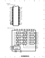
Page 75: ...RS P90 EW5 75 5 6 7 8 5 6 7 8 C D F A B E Pin Arrangement Chart Block Diagram Chart AD7564BRS ...
Page 79: ...RS P90 EW5 79 5 6 7 8 5 6 7 8 C D F A B E 1 2 3 GND IN OUT TA79L12F ...


