background image

RS-P90/EW5

78

1

2

3

4

1

2

3

4

C

D

F

A

B

E


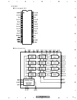
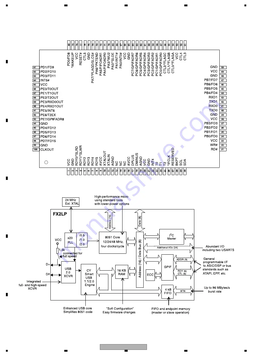
Pin Arrangement Chart

Block Diagram Chart

CY7C68013A-100AXC

Summary of Contents for RS-P90/EW5

Page 1: ...PIONEER EUROPE NV Haven 1087 Keetberglaan 1 9120 Melsele Belgium PIONEER ELECTRONICS ASIACENTRE PTE LTD 253 Alexandra Road 04 01 Singapore 159936 PIONEER CORPORATION 2006 RS P90 EW5 CRT3658 OPTICAL DIGITAL REFERENCE SYSTEM UNIVERSAL DIGITAL PREAMP RS P90 EW5 For details refer to Important Check Points for Good Servicing K ZZW OCT 2006 Printed in Japan ...

Page 2: ... and may void the If you are not qualified to the repair of this product properly and you should not risk trying to do so and refer the repair to a qualified service technician Service Precautions 1 You should conform to the regulations governing the product safety radio and noise and other regulations and should keep the safety during servicing by following the safety instructions described in th...

Page 3: ... the product Please check that neither solder debris nor screws remain inside the product 8 There should be no semi broken wires scratches melting etc on the coating of the power cord Damaged power cords may lead to fire accidents so please be sure that there are no damages If you find a damaged power cord please exchange it with a suitable one 9 There should be no spark traces or similar marks on...

Page 4: ...IDE PAGE 14 3 3 CONTROL UNIT 2 2 GUIDE PAGE 20 3 4 DSP PCB 1 2 GUIDE PAGE 26 3 5 DSP PCB 2 2 GUIDE PAGE 32 4 PCB CONNECTION DIAGRAM 38 4 1 CONTROL UNIT 38 4 2 DSP PCB 42 4 3 CONNECTOR PCB 46 5 ELECTRICAL PARTS LIST 47 6 ADJUSTMENT 63 6 1 JIG CONNECTION DIAGRAM 63 6 2 MASTER CLOCK ADJUSTMENT 64 7 GENERAL INFORMATION 65 7 1 DIAGNOSIS 65 7 1 1 DISASSEMBLY 65 7 1 2 CONNECTOR FUNCTION DESCRIPTION 67 7 ...

Page 5: ... 3 oct Gain 10 dB to 24 dB 0 5 dB LOW HPF frequency 25 Hz to 250 Hz 1 3 oct LPF frequency 250 Hz to 10 kHz 1 3 oct Gain 0 dB to 24 dB 0 5 dB MID HPF frequency 160 Hz to 10 kHz 1 3 oct LPF frequency 2 kHz to 20 kHz 1 3 oct Gain 0 dB to 24 dB 0 5 dB HIGH HPF frequency 1 6 kHz to 20 kHz 1 3 oct LPF frequency 8 kHz to 20 kHz 1 3 oct Gain 0 dB to 24 dB 0 5 dB Slope PASS 6 12 18 24 36 48 72 dB oct PASS ...

Page 6: ... the importance of the safety factor of the part Therefore when replacing be sure to use parts of identical designation Screw adjacent to mark on the product are used for disassembly For the applying amount of lubricants or glue follow the instructions in this manual In the case of no amount instructions apply as you think it appropriate 25 25 28 1 27 11 5 4 4 6 7 3 23 2 16 17 18 19 20 21 22 26 12...

Page 7: ...lene Bag CEG1364 12 Sub Carton CHG5726 13 Carton CHG5898 14 Contain Box CHL5898 15 Protector CHP3188 16 Owner s Manual English CRB2199 17 Owner s Manual Spanish CRB2200 18 Owner s Manual German CRB2201 19 Owner s Manual French CRB2202 20 Owner s Manual Italian CRB2203 21 Owner s Manual Dutch CRB2204 22 Owner s Manual Russian CRB2205 23 Warranty Card CRY1157 24 Clamper CNV1443 25 Bracket CND3195 26...

Page 8: ... 2 EXTERIOR A A B B A B C 47 50 51 15 12 13 20 17 5 4 3 6 6 21 1 1 1 1 1 55 56 58 44 16 45 52 53 54 2 2 2 18 18 22 22 22 22 41 25 28 26 27 57 57 57 42 37 39 24 38 38 35 23 43 31 11 19 10 32 29 30 36 34 33 46 48 49 8 14 9 13 20 6 6 40 40 40 15 2 ...

Page 9: ...801 CDE8049 28 Fuse 4 A CEK1001 29 Pin Jack CN103 CKB1072 30 Pin Jack CN104 CKB1072 31 Terminal CN901 CKE1060 32 Fuse Holder CN902 CKR1021 33 Connector CN301 CKS2600 34 Connector CN651 CKS3561 35 Connector CN601 CKS5071 36 Connector CN701 CKS5325 37 Holder CND3093 38 Holder CND3094 39 Screw PPZ20P060FTB 40 Screw PPZ30P080FTB 41 Terminal CN501 VNF1084 42 Terminal CN502 VNF1084 43 Terminal CN503 VNF...

Page 10: ...SPEED USB PERIPHERAL IC651 CY7C68013A 100AXC 18 RXD0 41 40 TXD0 DMINUS 17 USBDM USBDP DPLUS AVCC1 2 VCC1 9 RXD1 37 PB3 FD3 45 PB5 FD5 AUDIO CONTROL IC601 PEG169A IC150 TC7WH04FU TXD1 24 25 RXD1 27 P64 6 67 68 1 80 CNVSS 22 P71 23 RX TX P70 21 IPPW P76 15 P84 P00 P01 CLK4 SOUT4 79 62 61 53 SIN4 P05 P06 P26 43 51 65 63 P40 P30 P02 P04 50 49 46 45 P31 P32 P35 P36 44 47 48 42 1 3 5 7 5 CLKIN P37 P34 P...

Page 11: ...104 12VR 12bit DACx4 IC103 AD7564BRS IC111 LT1358CS8 IC113 1 2 LT1358CS8 IC113 2 2 LT1358CS8 6 EVOLENB EVOLSTB CLR SDIN CLKIN 15 16 LDAC 13 FSIN CLR 12 14 IOUT 1D 8 2 1 4 3 LLP LLO LLM ELDATA CLKIN IOUT 1C RFBD 9 5 RFBC VREFC 10 VREFD 12VL Q113 Q114 Q105 12VL 23 SLP SLM VREFB 19 VREFA 6 7 5 2 1 3 IC112 LT1358CS8 IOUT 1A 21 6 7 25 5 IOUT 1B RFBA 20 24 RFBB 2 1 3 6 7 5 SLO 12VL Q122 Q123 Q106 12VL 1...

Page 12: ... TCLK0 8 4 RCLK0 76 FLAG11 FLAG8 80 79 78 FLAG9 FLAG10 1 7 1 7 X4901 1 7 6 3 JTAG 2 4 2 1 5 10 13 4 9 12 3 6 8 11 IC4951 TC7WZ34FU IC4953 TC7SH04FUS1 IC4952 TC74VHC08FTS1 IRQ1 RESET CS WR OE2 OE1 EMU HBR HBG RFS1 DR1A DR1B FLAG3 FLAG0 DROB DROA IAD0 9 1 IAD131 IDAT0 31 1 IDAT0 7 1 JTEMU JTTRST DS1HBG DS1HBR DS1CS DS1WR DS1RST JTTMS JTTCK DS1DR1A DS1DR1B DS1STP DS1ER DS1RFS1 DSP1CLK DSP1 IC4301 2 2...

Page 13: ...17 HRP HRM IOUTR OUT_A 1 7 2 6 OUT_B IN_A IN_B SDOUTA SDINA SRC IC2202 SRC4184IPAG IC3013 TC7WZ34FU 64 58 LDATA 25 RCKIA RCKIB 60 53 1 3 7 5 LRCK3 62 LRCKOA LRCK4 51 49 20 29 SCK7 SCK8 LRCKOB BCK3 63 BCKOA BCK4 50 BCKOB BCKIA BCKIB IC3014 TC7WZ34FU 59 54 1 3 7 5 LRCKIA LRCKIB BCKO LRCKO A B C OUTLLR SDINB SDOUTB 55 SDATA 26 OUTSLR DATA DAC Mid IC2302 PCM1798DB IC2503 LT1358CS8 5 RST DMUTE DITRST S...

Page 14: ...1 2 A 1 2 C A a A a A b A b A a A b A b A a Large size SCH diagram Guide page Detailed page Note When ordering service parts be sure to refer to EXPLODED VIEWS AND PARTS LIST or ELECTRICAL PARTS LIST FUSE FUSE 1 2 B CN2101 1 2 B CN3201 C CONNECTOR PCB DSP UNIT Consists of DSP PCB CONNECTOR PCB ...

Page 15: ... component parts indicates the importance of the safety factor of the part Therefore when replacing be sure to use parts of identical designation Symbol indicates a resistor No differentiation is made between chip resistors and discrete resistors NOTE Symbol indicates a capacitor No differentiation is made between chip capacitors and discrete capacitors CONTROL UNIT 1 2 1 2 A 2 2 A ...

Page 16: ...mponent parts indicates the importance of the safety factor of the part Therefore when replacing be sure to use parts of identical designation Symbol indicates a resistor No differentiation is made between chip resistors and discrete resistors NOTE Symbol indicates a capacitor No differentiation is made between chip capacitors and discrete capacitors CONTROL UNIT 1 2 1 2 A 2 2 A ...

Page 17: ...RS P90 EW5 17 5 6 7 8 5 6 7 8 C D F A B E A a A b A b 1 2 3 4 5 6 1 2 B CN2401 ...

Page 18: ...RS P90 EW5 18 1 2 3 4 1 2 3 4 C D F A B E A b A a A a 1 2 A b 1 2 C 1 2 3 C CONNECTOR PCB DSP UNIT Consists of DSP PCB CONNECTOR PCB ...

Page 19: ...RS P90 EW5 19 5 6 7 8 5 6 7 8 C D F A B E A b A a A a 1 2 A b 1 2 3 4 5 6 FUSE FUSE 1 2 B CN2101 1 2 B CN3201 1 2 B C Consists of DSP PCB CONNECTOR PCB ...

Page 20: ...RS P90 EW5 20 1 2 3 4 1 2 3 4 C D F A B E 3 3 CONTROL UNIT 2 2 GUIDE PAGE A a 2 2 A 2 2 1 2 A 1 2 B CN2402 1 2 B CN2403 ...

Page 21: ...RS P90 EW5 21 5 6 7 8 5 6 7 8 C D F A B E A b 2 2 A 2 2 CONTROL UNIT 2 2 2 2 A ...

Page 22: ...RS P90 EW5 22 1 2 3 4 1 2 3 4 C D F A B E A a A b A b 2 2 1 2 CONTROL UNIT 2 2 2 2 A ...

Page 23: ...RS P90 EW5 23 5 6 7 8 5 6 7 8 C D F A B E A a A b A b 2 2 3 4 5 ...

Page 24: ...RS P90 EW5 24 1 2 3 4 1 2 3 4 C D F A B E A b A a A a 2 2 A b 2 2 1 2 1 2 A 1 2 B CN2402 ...

Page 25: ...RS P90 EW5 25 5 6 7 8 5 6 7 8 C D F A B E A b A a A a 2 2 A b 2 2 3 4 5 CN2402 1 2 B CN2403 ...

Page 26: ...RS P90 EW5 26 1 2 3 4 1 2 3 4 C D F A B E 3 4 DSP PCB 1 2 GUIDE PAGE B a 1 2 B 1 2 2 2 B 2 2 B 2 2 B 2 2 B B 2 2 B CN601 1 2 A CN302 1 2 A ...

Page 27: ...RS P90 EW5 27 5 6 7 8 5 6 7 8 C D F A B E B b 1 2 B 1 2 2 2 B CN101 2 2 A CN102 2 2 A CN801 1 2 A DSP PCB 1 2 1 2 B DSP UNIT Consists of DSP PCB CONNECTOR PCB ...

Page 28: ...RS P90 EW5 28 1 2 3 4 1 2 3 4 C D F A B E B a B b B b 1 2 1 2 3 2 2 B CN101 2 2 A CN102 2 2 A CN801 1 2 A DSP PCB 1 2 1 2 B DSP UNIT Consists of DSP PCB CONNECTOR PCB ...

Page 29: ...RS P90 EW5 29 5 6 7 8 5 6 7 8 C D F A B E B a B b B b 1 2 4 5 3 CN102 ...

Page 30: ...RS P90 EW5 30 1 2 3 4 1 2 3 4 C D F A B E B b B a B a 1 2 B b 1 2 1 2 3 2 2 B 2 2 B 2 2 B CN302 1 2 A ...

Page 31: ...RS P90 EW5 31 5 6 7 8 5 6 7 8 C D F A B E B b B a B a 1 2 B b 1 2 4 5 3 2 2 B 2 2 B CN601 1 2 A ...

Page 32: ...RS P90 EW5 32 1 2 3 4 1 2 3 4 C D F A B E 3 5 DSP PCB 2 2 GUIDE PAGE B a 2 2 B 2 2 1 2 B 1 2 B 1 2 B 1 2 B B 1 2 B ...

Page 33: ...RS P90 EW5 33 5 6 7 8 5 6 7 8 C D F A B E B b 2 2 B 2 2 DSP PCB 2 2 2 2 B 1 2 B 1 2 B 1 2 B 1 2 B 1 2 B DSP UNIT Consists of DSP PCB CONNECTOR PCB 1 2 B ...

Page 34: ...RS P90 EW5 34 1 2 3 4 1 2 3 4 C D F A B E B a B b B b 2 2 1 2 DSP PCB 2 2 2 2 B 1 2 B 1 2 B 1 2 B 1 2 B 1 2 B ...

Page 35: ...RS P90 EW5 35 5 6 7 8 5 6 7 8 C D F A B E B a B b B b 2 2 2 3 1 2 B DSP UNIT Consists of DSP PCB CONNECTOR PCB ...

Page 36: ...RS P90 EW5 36 1 2 3 4 1 2 3 4 C D F A B E B b B a B a 2 2 B b 2 2 1 2 1 2 B B ...

Page 37: ...RS P90 EW5 37 5 6 7 8 5 6 7 8 C D F A B E B b B a B a 2 2 B b 2 2 2 3 1 2 B 1 2 B 1 B ...

Page 38: ...lude all necessary parts for several destination For further information for respective destinations be sure to check with the schematic dia gram 2 Viewpoint of PCB diagrams 10 20 30 40 50 60 70 80 90 100 X 230 220 210 200 190 180 170 160 150 140 130 120 110 100 90 80 70 60 50 40 30 20 10 0 Y C CN513 B CN2101 B CN2402 B CN2403 B CN3201 IP BUS IN DIGITAL IN SUBWOOFE LOW OUT 11 7 9 10 6 5 4 3 2 1 4 ...

Page 39: ...S P90 EW5 39 5 6 7 8 5 6 7 8 C D F A B E A SIDE A 90 100 110 120 130 140 150 160 170 180 190 200 210 220 B CN2401 SUBWOOFER OUT LOW OUT MID OUT HIGH OUT POWER SUPPLY 5 7 8 6 1 3 4 2 5 7 8 6 1 3 4 2 1 2 3 ...

Page 40: ...RS P90 EW5 40 1 2 3 4 1 2 3 4 C D F A B E A A CONTROL UNIT 110 120 130 140 150 160 170 180 190 200 210 220 1 1 ...

Page 41: ...RS P90 EW5 41 5 6 7 8 5 6 7 8 C D F A B E A SIDE B 10 20 30 40 50 60 70 80 90 100 110 120 0 X 230 220 210 200 190 180 170 160 150 140 130 120 110 100 90 80 70 60 50 40 30 20 10 0 Y 1 1 1 1 ...

Page 42: ...RS P90 EW5 42 1 2 3 4 1 2 3 4 C D F A B E 4 2 DSP PCB B B DSP PCB 10 20 30 40 50 60 70 80 90 100 11 X 170 160 150 140 130 120 110 100 90 80 70 60 50 40 30 20 10 0 Y A CN102 A CN101 A CN302 A CN601 ...

Page 43: ...RS P90 EW5 43 5 6 7 8 5 6 7 8 C D F A B E B SIDE A 100 110 120 130 140 150 160 170 180 190 200 A CN801 A CN102 ...

Page 44: ...RS P90 EW5 44 1 2 3 4 1 2 3 4 C D F A B E B B DSP PCB 100 110 120 130 140 150 160 170 180 190 200 ...

Page 45: ...RS P90 EW5 45 5 6 7 8 5 6 7 8 C D F A B E B SIDE B 10 20 30 40 50 60 70 80 90 100 0 X 170 160 150 140 130 120 110 100 90 80 70 60 50 40 30 20 10 0 Y ...

Page 46: ...RS P90 EW5 46 1 2 3 4 1 2 3 4 C D F A B E 4 3 CONNECTOR PCB C SIDE B SIDE A C CONNECTOR PCB C CONNECTOR PCB 10 20 30 X 40 30 20 10 0 Y 10 20 30 X 40 30 20 10 0 Y A CN651 RESET ...

Page 47: ...A 33 52 IC HA12241FP IC 751 A 79 76 IC S 80827CNUA B8M IC 752 A 85 77 IC TC7SET04FUS1 IC 801 A 171 156 IC AN8011S IC 851 A 201 111 IC AN8011S IC 896 A 140 110 IC TA79L12F IC 897 A 135 110 IC TA79L12F IC 898 A 154 161 IC TA78L12F IC 899 A 141 143 IC TA78L12F IC 921 A 33 75 IC S 812C33AMC C2N IC 922 A 71 74 IC S 812C33AMC C2N IC 931 A 156 203 IC S 812C50AUA C3E IC 932 A 156 215 IC S 812C50AUA C3E IC...

Page 48: ...U D 982 A 80 59 Diode DAN202U L 310 A 75 21 Inductor LCTC1R8K2125 L 316 B 65 29 Inductor LCTC120K2125 L 651 A 18 81 Inductor LCTC1R8K2125 L 701 B 51 24 Inductor CTF1410 Circuit Symbol and No Part No L 710 A 35 47 Inductor LCTC4R7K1608 L 801 A 186 161 Inductor CTH1285 L 802 A 197 173 Inductor CTH1285 L 803 A 175 173 Inductor CTH1255 L 804 B 185 119 Inductor CTF1379 L 805 B 202 136 Inductor CTF1379 ...

Page 49: ...SE4700D R 201 A 123 108 RN1 10SE4700D R 202 A 115 114 RN1 10SE4701D R 203 A 120 103 RN1 10SE4701D R 204 B 120 108 RN1 10SC22R0D Circuit Symbol and No Part No R 205 B 120 105 RN1 10SC22R0D R 206 A 119 108 RN1 10SE1001D R 207 A 50 108 RN1 10SE4700D R 208 A 50 106 RN1 10SE4700D R 209 A 53 114 RN1 10SE4701D R 210 A 58 103 RN1 10SE4701D R 211 B 50 108 RN1 10SC22R0D R 212 B 50 105 RN1 10SC22R0D R 213 A ...

Page 50: ...D R 853 A 168 107 RS1 16S4302D R 854 B 167 129 RS1 16S1501D R 855 A 206 102 RS1 16S2400D Circuit Symbol and No Part No R 857 B 164 129 RS1 16S3002D R 863 B 202 132 RS1 16S472J R 864 B 206 132 RS1 16S472J R 865 B 188 126 RS1 16S472J R 866 B 184 126 RS1 16S472J R 867 A 194 107 RS1 16S101J R 868 A 197 118 RS1 16S3002D R 869 A 197 116 RS1 16S101J R 870 B 195 107 RS1 16S3002D R 871 A 201 116 RS1 16S224...

Page 51: ...128 CKSQYB104K50 C 194 A 88 128 CCSQCH470J50 C 195 A 86 125 CCSQCH470J50 C 196 B 91 121 CKSQYB104K50 C 197 A 86 165 CCSQCH220J50 C 198 B 86 157 CKSQYB104K50 C 199 A 91 165 CCSQCH220J50 Circuit Symbol and No Part No C 200 B 86 164 CKSQYB104K50 C 201 A 81 165 CCSQCH220J50 C 202 B 76 164 CKSQYB104K50 C 203 A 76 165 CCSQCH220J50 C 204 A 76 141 100 µF 16 V CCH1702 C 205 B 71 128 CKSQYB104K50 C 206 B 74...

Page 52: ...5 C 856 A 158 119 CEHAZL101M25 C 857 B 165 124 CKSRYB104K50 Circuit Symbol and No Part No C 859 A 165 127 CEHAZL560M50 C 860 A 166 119 CEHAZL560M50 C 863 B 206 130 CCSRCH331J50 C 864 B 184 128 CCSRCH331J50 C 865 B 193 99 CKSRYB104K50 C 866 B 195 104 CKSQYB475K10 C 867 A 199 119 CKSQYB475K10 C 868 A 201 117 CKSRYB473K50 C 869 A 201 105 CKSRYB473K50 C 870 A 210 111 CEAL4R7M35 C 871 A 210 105 CEJQ330...

Page 53: ...nsistor 2SC4226 Q 3002 A 134 102 Transistor 2SD1767 Q 3003 A 119 111 Transistor 2SD1767 Q 3004 A 134 97 Transistor 2SC2412K Q 3005 A 123 113 Transistor 2SC2412K D 2201 B 74 89 Diode Network DA204U D 2202 B 61 104 Diode Network DA204U D 2203 B 62 100 Diode Network DA204U D 2204 B 68 89 Diode Network DA204U D 2205 A 65 102 Diode Network DA204U D 2206 A 69 105 Diode Network DA204U D 2251 A 53 105 Dio...

Page 54: ...8 A 68 98 RN1 16SC47R0D R 2210 B 79 103 RS1 16S0R0J R 2211 B 81 103 RS1 16S0R0J R 2213 B 84 103 RS1 16S0R0J R 2214 A 87 96 RS1 16S101J R 2215 A 87 98 RS1 16S103J R 2216 B 83 94 RS1 16S0R0J R 2218 B 81 94 RS1 16S0R0J Circuit Symbol and No Part No R 2219 A 81 89 RS1 16S103J R 2221 B 76 94 RS1 16S0R0J R 2240 A 87 100 RS1 16S103J R 2241 A 78 107 RS1 16S0R0J R 2242 B 79 94 RS1 16S0R0J R 2251 A 55 105 R...

Page 55: ...89 88 RN1 16SC47R0D R 3037 A 48 73 RN1 16SC47R0D R 3039 B 47 61 RN1 16SC47R0D R 3040 A 22 87 RN1 16SC47R0D R 3041 A 22 89 RN1 16SC47R0D Circuit Symbol and No Part No R 3042 B 50 62 RN1 16SC47R0D R 3043 A 21 103 RN1 16SC47R0D R 3044 A 21 105 RN1 16SC47R0D R 3045 A 22 93 RN1 16SC47R0D R 3046 A 22 94 RN1 16SC47R0D R 3047 A 21 98 RN1 16SC47R0D R 3048 A 21 100 RN1 16SC47R0D R 3051 A 89 90 RS1 16S0R0J R...

Page 56: ...4088 A 113 30 RS1 16S0R0J R 4089 A 112 30 RS1 16S0R0J R 4090 A 110 30 RS1 16S0R0J Circuit Symbol and No Part No R 4091 A 109 30 RS1 16S0R0J R 4092 A 107 30 RS1 16S0R0J R 4093 A 106 30 RS1 16S0R0J R 4094 A 104 30 RS1 16S47R0D R 4095 A 103 30 RS1 16S47R0D R 4096 A 101 30 RS1 16S47R0D R 4097 A 100 30 RS1 16S47R0D R 4098 A 98 30 RS1 16S47R0D R 4099 A 97 30 RS1 16S47R0D R 4100 A 95 30 RS1 16S47R0D R 41...

Page 57: ...S0R0J R 4391 A 177 30 RS1 16S0R0J R 4392 A 176 30 RS1 16S0R0J R 4393 A 173 30 RS1 16S47R0D Circuit Symbol and No Part No R 4394 A 171 30 RS1 16S47R0D R 4395 A 170 30 RS1 16S47R0D R 4396 A 168 30 RS1 16S47R0D R 4397 A 167 30 RS1 16S47R0D R 4398 A 165 30 RS1 16S47R0D R 4399 A 164 30 RS1 16S47R0D R 4400 A 162 30 RS1 16S47R0D R 4401 A 161 30 RS1 16S47R0D R 4402 A 159 30 RS1 16S47R0D R 4403 A 158 30 RS...

Page 58: ...161 118 RS1 16S0R0J R 4693 A 164 118 RS1 16S47R0D R 4694 A 165 121 RS1 16S47R0D R 4695 A 166 118 RS1 16S47R0D R 4696 A 167 121 RS1 16S47R0D Circuit Symbol and No Part No R 4697 A 168 118 RS1 16S47R0D R 4698 A 169 121 RS1 16S47R0D R 4699 A 170 118 RS1 16S47R0D R 4700 A 171 121 RS1 16S47R0D R 4701 A 172 118 RS1 16S47R0D R 4702 A 173 121 RS1 16S47R0D R 4703 A 174 118 RS1 16S47R0D R 4704 A 175 121 RS1...

Page 59: ... 57 141 CKSQYB104K50 Circuit Symbol and No Part No C 2357 B 17 141 CKSQYB104K50 C 2358 B 26 141 CKSQYB104K50 C 2361 A 104 143 47 µF 25 V CCH1544 C 2362 A 124 135 47 µF 25 V CCH1544 C 2363 A 124 143 47 µF 25 V CCH1544 C 2364 A 73 143 47 µF 25 V CCH1544 C 2365 A 93 135 47 µF 25 V CCH1544 C 2366 A 93 143 47 µF 25 V CCH1544 C 2367 A 42 143 47 µF 25 V CCH1544 C 2368 A 62 135 47 µF 25 V CCH1544 C 2369 A...

Page 60: ...04K16 C 3044 A 24 92 CKSRYB104K16 C 3045 A 26 97 CKSRYB104K16 C 3046 A 24 97 CKSRYB104K16 C 3047 A 54 62 CKSRYB104K16 Circuit Symbol and No Part No C 3048 A 52 62 CKSRYB104K16 C 3049 A 54 68 CKSRYB104K16 C 3050 A 52 68 CKSRYB104K16 C 3051 A 59 103 CKSRYB104K16 C 3052 A 59 101 CKSRYB104K16 C 3053 A 59 96 CKSRYB104K16 C 3054 A 59 94 CKSRYB104K16 C 3055 A 64 113 CKSRYB104K16 C 3056 A 66 113 CKSRYB104...

Page 61: ...192 42 CKSRYB104K16 C 4340 B 192 38 CKSRYB104K16 C 4341 B 202 51 CKSRYB104K16 Circuit Symbol and No Part No C 4342 B 203 42 CKSRYB104K16 C 4343 B 203 38 CKSRYB104K16 C 4344 B 203 33 CKSRYB104K16 C 4345 B 161 23 CKSRYB104K16 C 4346 B 156 23 CKSRYB104K16 C 4347 B 175 15 CKSRYB104K16 C 4348 B 161 15 CKSRYB104K16 C 4349 B 156 15 CKSRYB104K16 C 4350 B 154 15 CKSRYB104K16 C 4351 B 179 48 CKSRYB103K50 C ...

Page 62: ...SRYB104K16 C 4810 A 202 136 CEJQ470M10 C 4811 B 203 133 CKSRYB104K16 C 4812 B 194 129 CKSRYB104K16 C 4813 A 194 129 CASA470M10 C 4814 B 202 129 CKSRYB104K16 C 4815 A 202 129 CASA470M10 C 4901 A 130 87 CASA470M10 C 4902 B 130 86 CKSRYB104K16 C 4903 B 130 81 CKSRYB104K16 C 4904 A 130 80 CASA470M10 C 4905 A 114 81 CKSRYB104K16 C 4906 A 123 87 CCSRCH180J50 C 4907 A 112 86 CCSRCH220D50 C 4912 A 124 79 ...

Page 63: ...RS P90 EW5 63 5 6 7 8 5 6 7 8 C D F A B E 6 ADJUSTMENT 6 1 JIG CONNECTION DIAGRAM CN601 CN302 CONTROL UNIT DSP UNIT CN3201 CN2101 GGD1028 GGD1288 ...

Page 64: ...following requirements and make adjustment within 3 or 4 minutes from the start of such operation Measuring instruments to be used Frequency counter or high frequency probe Master clock adjustment The adjustment for service should be served in the product condition instead of in the unit condition Otherwise it would require jigs Remove the top case front panel and the shield case of the DSP unit s...

Page 65: ...ENERAL INFORMATION 7 1 DIAGNOSIS 7 1 1 DISASSEMBLY Panel 1 1 Fig 1 Fig 2 Removing the Panel Fig 1 Removing the Holder Fig 2 Remove the six screws and then remove the two Panels Remove the screw and then remove the Holder 1 1 1 1 1 1 Panel Holder 1 ...

Page 66: ...the DSP Unit Fig 3 Removing the Control Unit Fig 4 Disconnect the five connectors Remove the three screws and then remove the DSP Unit Straighten the tabs at four locations indicated Remove the three screws and then remove the Control Unit 1 1 1 1 1 1 1 1 1 2 2 2 2 2 2 Control Unit ...

Page 67: ...ON DESCRIPTION PRE SUBWOOFER OUT PRE LOW OUT PRE MID OUT PRE HIGH OUT B REMOTE B UP GND 1 BUS 2 GND 3 GND 4 NC 5 BUS 6 GND 7 BUS L INPUT 8 ASENB 9 BUS R INPUT 10 BUS R INPUT 11 BUS L INPUT 1 2 3 4 5 6 7 8 9 10 11 IP BUS DIGITAL IN 1 2 3 4 1 OPIG 2 OPI 3 GND 4 OPI5V ...

Page 68: ...gram Chart DIR1703ES1 DIR1703ES1 SRC4184IPAG PCM1798DB LT1358CS8 NJM431U TC7WZ34FU TC7SZU04FU TC7SH04FUS1 TC7SH32FUS1 TC74LCX541FTS1 TC74VHC541FTS1 TC74VHC08FTS1 EPF6016ATI144 3S1 ADSP 21065LCS240S1 AD7564BRS PEG169A HA12241FP TC7SET04FUS1 S 812C33AMC C2N CY7C68013A 100AXC TA79L12F ...

Page 69: ...B Control SRC B SPI Port and Reset IFMTB0 IFMTB1 IFMTB2 OFMTB0 OFMTB1 OWLB0 OWLB1 BYPB H S RST VIO DGND VDD18 2 VDD33 2 DGND REGEN LRCKIA BCKIA SDINA RCKIA Input Serial Port Digital De Emphasis and Interpolation Filters Re Sampler Digital Decimation Filter Output Serial Port LRCKOA BCKOA SDOUTA TDMIA Rate Estimator fsOUT RDYB fsIN RATIOB LRCKIB BCKIB SDINB RCKIB Input Serial Port Digital De Emphas...

Page 70: ...RS P90 EW5 70 1 2 3 4 1 2 3 4 C D F A B E Pin Arrangement Chart PCM1798DB ...

Page 71: ... 1 2 3 4 5 6 7 8 TC7WZ34FU VCC NC IN A OUT Y GND 5 4 1 3 2 TC7SZU04FU TC7SH04FUS1 1 IN B 2 IN A 3 GND 4 OUT Y 5 VCC TC7SH32FUS1 1 2 3 4 5 6 7 8 9 10 20 19 18 17 16 15 14 13 12 11 OE1 A1 A2 A3 A4 A5 A5 A6 A7 A8 GND VCC OE2 Y1 Y2 Y3 Y4 Y5 Y6 Y7 Y8 TC74LCX541FTS1 TC74VHC541FTS1 14 VCC 13 4B 12 4A 11 4Y 10 3B 9 3A 8 3Y 1 1A 2 1B 3 1Y 4 2A 5 2B 6 2Y 7 GND TC74VHC08FTS1 ...

Page 72: ...RS P90 EW5 72 1 2 3 4 1 2 3 4 C D F A B E Pin Arrangement Chart EPF6016ATI144 3S1 ...

Page 73: ...RS P90 EW5 73 5 6 7 8 5 6 7 8 C D F A B E Block Diagram Chart ...

Page 74: ...RS P90 EW5 74 1 2 3 4 1 2 3 4 C D F A B E Pin Arrangement Chart Block Diagram Chart ADSP 21065LCS240S1 ...

Page 75: ...RS P90 EW5 75 5 6 7 8 5 6 7 8 C D F A B E Pin Arrangement Chart Block Diagram Chart AD7564BRS ...

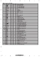
Page 76: ...O C O Test program serial data output 29 RXD0 Test program serial data input 30 CLK0 I Test program serial clock input 31 33 NC Not used 34 P55 Flash write mode enable input 39 P50 35 38 NC Not used DSP IC power control output 40 P43 Test program enable input 41 P42 I C C C O I Power amp error input 42 P41 Hardware mute request output 43 P40 DSP stop request input 44 P37 I DIR reset input 45 P36 O...

Page 77: ...2 P05 PLD config status input 63 P04 64 NC Not used 65 P02 PLD reset data output 66 P01 PLD chip enable output PLD chip enable output 61 80 1 20 21 40 41 60 PEG169A Pin No Pin Name Format I O Function and Operation Format Meaning C CMOS N N ch open drain 1 3 2 S1 R out S2 GND BUS BUS VCC stb 4 5 6 7 8 BIAS DRIVER OUTPUT current COM RECEIVER OUTPUT HA12241FP 1 2 3 4 5 GND VCC IN A NC OUT Y TC7SET04...

Page 78: ...RS P90 EW5 78 1 2 3 4 1 2 3 4 C D F A B E Pin Arrangement Chart Block Diagram Chart CY7C68013A 100AXC ...

Page 79: ...RS P90 EW5 79 5 6 7 8 5 6 7 8 C D F A B E 1 2 3 GND IN OUT TA79L12F ...

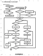
Page 80: ...rror ON DSPPW on Pin40 H Normal Mute OFF Pin42 L PLD DSP initialization About 3 seconds Mute off Pin42 L DSPPW on Pin40 H OFF DSPPW off Pin40 L Mute on Pin42 H Power on commond DSP error PW lamp on and off DIT reset Pin47 L Main loop SYSTEM RESET Bup Acc check Acc Pin15 Bup Pin16 Microcomputer dispatch stop Power saving mode Pin16 Low and Pin15 Low Pin16 Low and Pin15 Low Unit check program start ...

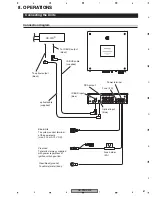
Page 81: ...7R To IP BUS output black To optical output black Fuse 4 A Fuse holder 4 A Power terminal Clear red To terminal always supplied with power regardless of ignition switch position Clear black ground To vehicle metal body Blue white To system control terminal of the power amp max 300 mA 12 V DC RCA output Connecting the Units Connection diagram ...

Page 82: ... 1 2 3 4 C D F A B E Connecting the RCA input amplifier Tweeter Mid range Woofer Subwoofer White White Red Red Power amplifier Power amplifier Power amplifier Power amplifier For system remote control Blue white Blue white ...

Page 83: ...RS P90 EW5 83 5 6 7 8 5 6 7 8 C D F A B E ...

Page 84: ...RS P90 EW5 84 1 2 3 4 1 2 3 4 C D F A B E Jigs List 2 Pin Extension cable 32 Pin FFC GGD1028 GGD1288 Control Unit CN302 DSP Unit CN2101 Control Unit CN601 DSP Unit CN3201 Name Jig No Remarks ...

Reviews: