background image

S-FCRW210-K
S-FCRW710-K

13

6. PCB PARTS LIST

NOTES :


Parts marked by “ NSP ” are generally unavailable because they are not in our Master Spare Parts List.

 The mark 

 found on some component parts indicates the importance of the safety factor of the part. Therefore, when replacing,

be sure to use parts of identical designation.

 When ordering resistors, first convert resistance values into code form as shown in the following examples.

Ex. 1 When there are 2 effective digits (any digit apart from 0), such as 560 ohm and 47k ohm (tolerance is shown by

=

 5%, and K 

=

 10%).

560 


=

 56 x 10 

1


=

 561 ................................................... RD1/4PU 

5 6 1

 J

47k 


=

 47 x 10 

3


=

 473 ................................................... RD1/4PU 

4 7 3

 J

0.5 


=

 R50 ....................................................................... RN2H


Â


5 0

 K


=

 1R0 .......................................................................... RS1P 


0

 K

Ex. 2 When there are 3 effective digits (such as in high precision metal film resistors).
5.62k 

 = 562 x 10 

1

 = 5621 ........................................... RN1/4PC 

5 6 2 1

 F

Mark

No.

Description

Parts No.

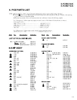
LIST OF PCB ASSEMBLIES

NSP

SUBWOOFER AMP

AWK7722

AMP ASSY

AWU7760

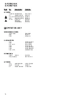
OPERATION ASSY AWU7761

A

 AMP ASSY

SEMICONDUCTORS

IC41,IC51

NJM2904M

IC43

NJM7806FA

IC44

NJM7906FA

Q52

2SA1009A(K)

Q22, Q31

2SA1037K

Q11, Q12

2SA1625

Q51

2SC2333(K)

Q201, Q23

2SC2412K

Q53, Q54

 2SC4060

Q56, Q58

2SK246

Q57

2SK246

Q55

DTA124EK

Q21

IRF640

D52, D55

11EQS06

D23, D53

1SS133

D26

20E2-FC

D35

DAN217

D15

G3SBA20L

D17, D18, D37

MTZJ15A

D21

MTZJ18

D25

MTZJ20

D36

MTZJ6.2B

D27

MTZJ6.8B

D101–D104,D16,D24,D28

S5688G

D31–D34

S5688G

D51

S5688G

TH22

AEX7005

PC41

TLP621(Y)

Mark

No.

Description

Parts No.

COILS AND FILTERS

L1

ATF-151

TRANSFORMERS

T12

ATT7058

T11

ATT7059

CAPACITORS

C2

(0.033mF/250V)

ACE7023

C13, C14 (2200mF/100V)

ACH7140

C19, C20

CCSL470K2H

C42–C45

CEAT100M50

C224, C31, C32, C51

CEAT101M16

C101

CEAT101M25

C61

CEAT1R0M50

C33, C34

CEAT221M16

C36

CEAT330M16

C39

CEAT470M16

C63

CEATR10M50

C22

CEHAT1R0M50

C62

CEHAT2R2M50

C21

CEHAT470M50

C53, C54

CKCYB102K2H

C23

CKSQYB103K50

C64

CKSQYB223K50

C41

CKSQYB472K50

C25–C27, C46

CKSQYB473K50

C24

CQMA153K2E

RESISTORS

R67

RD1/4PU223J

R26

RS1/10S101J

R57, R58

RS1/10S221J

VR41

(4.7k

Ω 

)

VCP1154

Other Resistors

RS1/10S

&&&

J

Summary of Contents for S-FCRW210-K

Page 1: ... DIAGRAMS 6 5 PCB CONNECTION DIAGRAM 10 6 PCB PARTS LIST 13 7 ADJUSTMENT 15 8 PANEL FACILITIES 16 9 SPECIFICATIONS 17 Service Manual ORDER NO PET01007 HOME THEATER LOUDSPEAKER SYSTEM S FCRW210 K S FCRW710 K L E D O M E P Y T S T E N O P M O C R E W O P T N E M E R I U Q E R K R A M E R C X U K C X C K R E F O O W B U S R E T N E C T N O R F E T I L L E T A S R A E R E T I L L E T A S K 0 1 2 W R C...

Page 2: ...valent between the earth ground and all exposed metal parts of the appliance input output terminals screwheads metal overlays control shaft etc Plug the AC line cord of the appliance directly into a 120VAC 60Hz outlet and turn theAC power switch on Any current measured must not exceed 0 5mA ANY MEASUREMENTS NOT WITHIN THE LIMITS OUTLINED ABOVEARE INDICATIVE OFAPOTENTIALSHOCK HAZARD AND MUST BE COR...

Page 3: ... use parts of identical designation Parts marked by are not always kept in stock Their delivery time may be longer than they may be unavailable 3 1 PACKING Parts List Mark No Description Parts No 1 Instruction Manual 277854 2 RCA Pin Cable 277681 3 Speaker Wire PNK WHT 277636 4 Speaker Wire BLU WHT 277641 5 Speaker Wire YEL WHT 277656 6 Speaker Wire ORG WHT 277661 7 Speaker Wire GRN WHT 277676 8 S...

Page 4: ...fer Gasket 277745 8 Port Gasket 277750 9 Screw for Woofer AMP 278015 3 2 2 SATELLITE SPEAKER Parts List Mark No Description Parts No 1 Satellite Front Center Assy 210 278020 2 Satellite Front Center Assy 710 278164 3 Satellite Rear Assy 210 278060 4 Satellite Rear Assy 710 278184 5 Metal Grill with Logo 278040 6 Bracket 277403 7 Screw for Bracket 278055 SCHEMATIC DIAGRAM YEL BLK Woofer RED BLK RED...

Page 5: ...4 2 OPERATION ASSY AWU7761 3 Operation Panel ANC8006 NSP 4 Heat Sink ANH7117 5 Screw ABA1052 6 AMP ASSY AWU7760 7 Screw BPZ30P080FZK 8 Rear Case Assy AXG7085 9 Cord Stopper CM 22C 10 Air Packing L AEB7172 11 Air Packing S AEB7174 Mark No Description Parts No 12 Rear Case AMC7039 13 Mica Sheet AEE7033 14 Vol Knob Assy PXA1621 NSP 15 Vol Knob PAC1951 NSP 16 Spring PBH1229 17 Fuse FU 1 5A REK1067 18 ...

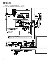
Page 6: ... P F IN to Photo Coupler D101 D104 S5688G Offset Cancel Photo Coupler to Power AMP Ó Ó dBv 30 20 10 0 8dB 6dB 6dB 1 5 10 18 5dBv 50Hz 120mV IC 201 NJM2904M FU1 REK1067 5A IC 201 NJM2904M IC 41 NJM2904M IC 44 NJM7906FA IC 43 NJM7806FA D31 D34 S5688G 16v 16v D201 T11 T12 D33 D31 D32 D34 PC41 TLP621 Y JA201 2 5 7 2 1 1 Q201 2SC2412K OPERATON ASSY AWU7761 AMP ASSY AWU7760 A 12 6v 12 6v 6v 6v 6 1v 0 v ...

Page 7: ...er Charge balance and DC feedback Buff Clip Det AC ON OFF Mute Slow Start FET Thermal Detection Ó Ó 34 5dB 34 5dBv 53 V Total Gain 53dB 50Hz IC 41 NJM2904M Q53 Q54 2SC4060 Q21 IRF640 Q55 DTA124EK D15 G3SBA20L C13 C14 Q56 2SK246 Q58 2SK246 6 7 AMP ASSY AWU7760 A 84v 84v 168v D D E E ...

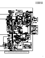
Page 8: ...OPERATION ASSYS 6 B OPERATION ASSY NOTE FOR FUSE REPLACEMENT FOR CONTINUED PROTECTION AGAINST RISK OF FIRE REPLACE WITH SAME TYPE AND RATINGS ONLY CAUTION AC POWER CORD KUC PDG1064 KUC 60Hz AC120V POWER TRANSFORMER AUDIO SIGNAL SIGNAL ROUTE ...

Page 9: ...RW210 K S FCRW710 K 9 ADX7356 6 A AMP ASSY CAUTION FOR CONTINUED PROTECTION AGAINST RISK OF FIRE REPLACE ONLY WITH SAME TYPE NO 491005 FOR IC21 4910003 FOR IC11 IC12 MFD BY LITTELFUSE INC POWER TRANSFORMER ...

Page 10: ...Symbol in Schematic Diagrams Part Name Transistor Transistor with resistor Field effect transistor B C E B C E B C E D G S B C E B C E B C E D G S D G S 3 The parts mounted on this PCB include all necessary parts for several destination For further information for respective destinations be sure to check with the schematic diagram 4 Viewpoint of PCB diagrams Resistor array 3 terminal regulator Cap...

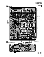
Page 11: ...S FCRW210 K S FCRW710 K 11 OPERATION ASSY B AMP ASSY A AC POWER CORD ANP7319 C Q51 IC11IC12 Q53 Q54 Q57 IC21 Q21 Q12 Q11 Q52 Q56 Q58 IC43 IC44 VR41 To Speaker SIDE A A B ...

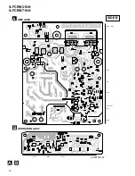
Page 12: ...S FCRW210 K S FCRW710 K 12 A B SIDE B OPERATION ASSY B AMP ASSY A ANP7319 C IC203 IC202 IC201 Q71 Q22 Q23 Q72 Q31 Q201 IC51 IC41 Q55 ...

Page 13: ...722 AMP ASSY AWU7760 OPERATION ASSY AWU7761 A AMP ASSY SEMICONDUCTORS IC41 IC51 NJM2904M IC43 NJM7806FA IC44 NJM7906FA Q52 2SA1009A K Q22 Q31 2SA1037K Q11 Q12 2SA1625 Q51 2SC2333 K Q201 Q23 2SC2412K Q53 Q54 2SC4060 Q56 Q58 2SK246 Q57 2SK246 Q55 DTA124EK Q21 IRF640 D52 D55 11EQS06 D23 D53 1SS133 D26 20E2 FC D35 DAN217 D15 G3SBA20L D17 D18 D37 MTZJ15A D21 MTZJ18 D25 MTZJ20 D36 MTZJ6 2B D27 MTZJ6 8B ...

Page 14: ...01 TERMINAL RKC 061 PCB BINDER VEF1040 B OPERATION ASSY SEMICONDUCTORS IC201 IC203 NJM2904M D201 AEL7014 D202 MTZJ6 2B CAPACITORS C214 CCSQCH330J50 C201 CEAT100M50 C211 C213 CEAT101M16 C209 CFTLA154J50 C228 CKSQYB473K50 C205 CKSQYB682K50 C227 C210 CQMBA473J50 RESISTORS VR201 50kΩ ACS7033 Other Resistors RS1 10S J OTHERS J201 JUMPER WIRE D20PYY0425E JA201 1P JACK VKB1077 4P CABLE HOLDER 51048 0400 ...

Page 15: ...meter 2 Oscilloscope 3 Attenuator 4 Low frequency oscillator 7 7 7 7 7 GAIN Adjustment 1 Decrease the level of the Adjustment Variable resistors VR for the channel to adjusted 2 Increase LEVEL VOLUME maximum 3 Adjust GAIN VR41 volume Apply the signal to the Line IN of JA201 As the gain from IN to SPEAKER OUT 53dB freq 50 Hz input of 10mVrms to Input results in output of 0 72 W 4 5 Vrms 28 W at SPE...

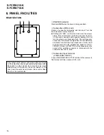
Page 16: ...h frequencies Caution must be taken here since the amplifier and speaker of the S FRCW210 K and S FCRW710 K will be clipped when the output of the amplifier or receiver is increased with the subwoofer level set to MAX 3 Subwoofer input terminal LINE LEVEL INPUT Connect SUBWOOFER OUTPUT terminal of the receiver to this terminal with the accessory RCA cord 8 PANEL FACILITIES If the output of the rec...

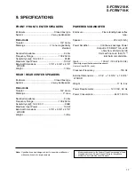
Page 17: ...Weight 1 5 lbs REAR REAR CENTER SPEAKERS Enclosure Closed box type System 2 way loudspeaker Drive Units Tweeter 3 4 dome Midrange 3 cone Nominal Impedance 8 ohm Frequency Range 100 20k Hz Sensitivity spl 1m 2 83 V 85dB Maximum Input Power 100 W External Dimensions 3 7 8 x 6 3 8 x 4 7 8 WXHXD Weight 1 2 lbs POWERED SUBWOOFER Enclosure Floor standing bass reflex type Speaker 20 cm 8 inch Power Ampli...

Reviews: