background image

7

S-HS01

Mark   No.           Description                     Part No.

1

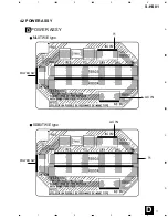
POWER ASSY

See Contrast Table(2)

2

MAIN ASSY

APE0127C011

3

LED Assy

APE0127C031

4

JACK+VOL. ASSY

APE0127C021


5

AC Power Cord

See Contrast Table(2)


6

Power Switch (SW901)

MSP0001-A18


7

Fuse (F903)

See Contrast Table(2)


8

Fuse (F901, F902)

KSA2400-104

                                  (T4AL/250V)


9

Power Trans (T1)

See Contrast Table(2)

10

Cover

BPC0029C001

11

SW Cover

BPC0042-001

12

Front Cabinet

BPF5027C001

13

Volume Knob

BPK5018-004

14

Power Knob

BPK6018C001

15

Port Tube Assy

AFA0033C001

NSP

16

Port Tube

BPR0014CESO

NSP

17

Paper Tube

DPP5648-088

NSP

18

Sponge

IVE0133C001

NSP

19

Sponge

IVE0113C001

20

Bushing

DBU0002-101

21

Tubing

DTB0800-034

22

Speaker

FTW5054-311

NSP

23

Rear Plate

See Contrast Table(2)

24

Speaker Grille

GSP0028C001

25

Screw

H011009-310

26

Screw

TNC30P120FZK

27

Screw

H011009-322

28

Screw

TNC35P140FZK

29

Screw

PRZ20P060FMC

30

Screw

PCZ30P080FZK

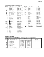
(1) POWERED SUBWOOFER PARTS LIST

Mark   No.           Description                     Part No.

NSP

31

Sponge

IVE0073C001

32

Sponge

IVE0074C001

NSP

33

Sponge

IVE0090C001

34

Sponge

IVE0091C001

35

Sponge

IVE0101C001

NSP

36

Sponge

IVE0103C001

NSP

37

PVC Plate

BNP0049C001

38

Rubber Pad

BRB0029C001

NSP

39

Catch

DCA1116-001

NSP

40

Twist Lock

DMP2001-001

41

Spacer

DSS0003-003

42

Screw

BYC30P250FMC

43

Screw

AMZ40P250FMC

44

Nut

NB40FMC

45

Washer

WH40FUC

46

Heat Sink

GAL0063C001

47

Heat Sink

GAL0107-004

48

Mica Sheet

GMI0006-001

49

PCB Bracket

GSE0093-002

50

Screw

ABZ30P120FZK

51

Screw

PBZ30P060FZK

52

Rear Panel Cover

See Contrast Table(2)


53

Voltage Selector

See Contrast Table(2)

Mark

(2) CONTRAST TABLE

S-HS01/MLXTW/E and S-HS01/SDBXTW/E are constructed the same except for the following:

Part No.

Remarks

Symbol and Description

No.

1

POWER ASSY

APE0141C003

APE0141C002

5

AC Power Cord

2559-022G22

47455-D77A

7

Fuse (F903)

KSA2100-104

KSA2200-104

(T1AL/250V)

(T2AL/250V)

9

Power Trans (T1)

TTH2301C010

TTH2402C010

NSP

23

Rear Plate

GSP0021C003

GSP0021C002

52

Rear Panel Cover

GSP0030C001

Not used

53

Voltage Selector (SW902)

Not used

MSR1001-001

S-HS01/MLXTW/E

S-HS01/SDBXTW/E

Summary of Contents for S-HS01

Page 1: ...LITE SPEAKER POWERED SUBWOOFER S HS01 1 SAFETY INFORMATION 2 2 EXPLODED VIEWS AND PARTS LIST 3 3 SCHEMATIC DIAGRAM 8 4 PCB CONNECTION DIAGRAM 10 5 PCB PARTS LIST 13 6 ADJUSTMENT 13 CONTENTS 7 GENERAL INFORMATION 14 7 1 DISASSEMBLY 14 8 PANEL FACILITIES AND SPECIFICATIONS 15 T ZZV OCT 2001 Printed in Japan THIS MANUAL IS APPLICABLE TO THE FOLLOWING MODEL S AND TYPE S Type Model S HS01 MLXTW E SDBXT...

Page 2: ...vident from visual inspection nor the protection afforded by them necessarily can be obtained by using replacement components rated for voltage wattage etc Replacement parts which have these special safety characteristics are identified in this Service Manual Electrical components having such features are identified by marking with a on the schematics and on the parts list in this Service Manual T...

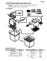
Page 3: ...o Mark No Description Part No 1 RCA Plug Cord VRC0001 A06 2 Opearting Instructions SRD1229 English Chinese MLXTW E type 2 Opearting Instructions SRD1230 English Chinese Spanish SDBXTW E type 3 Protector ITF0114C001 4 Packing Case MLXTW E type SHG2395 4 Packing Case SDBXTW E type SHG2396 2 1 PACKING PACKING PARTS LIST NSP 5 Speaker Cord Set SEA1573 6 Speaker Cord Front Center SDS1086 7 Speaker Cord...

Page 4: ...4 S HS01 2 2 SATELLITE SPEAKER 3 16 Rear side of the badge 2 76 210 11 13 13 7 10 14 1 9 8 6 4 red 5 white 12 15 ...

Page 5: ...3 8 Packing SEC1574 NSP 9 Input Terminal SKX1076 NSP 10 Stamped Model Label SME3269 NSP 10 Label Back SAN3045 NSP 11 Acoustic Absorbent SMT1137 12 Speaker A142CU54 51F 13 Screw PPZ40P080FZK 14 Fung Nut M5 SBN1044 15 Packing SEC1580 NSP 16 Outside Stopper Ring SBG1005 SATELLITE SPEAKER PARTS LIST SPEAKER CORD CONNECTING DIAGRAM Speaker Cord SDB1144 SDB1145 INPUT RED WHITE Full Range ...

Page 6: ... 7 41 40 42 38 38 30 30 47 51 35 32 49 4 50 28 28 28 28 16 5 25 25 25 30 13 52 50 2 8 44 44 48 46 10 33 31 23 45 45 34 22 28 28 9 6 3 29 12 18 16 26 26 15 17 39 39 39 36 21 24 27 27 A C D B 28 28 28 28 16 5 53 25 25 25 30 13 23 SDBXTW E type MLXTW E type ...

Page 7: ... Mark No Description Part No NSP 31 Sponge IVE0073C001 32 Sponge IVE0074C001 NSP 33 Sponge IVE0090C001 34 Sponge IVE0091C001 35 Sponge IVE0101C001 NSP 36 Sponge IVE0103C001 NSP 37 PVC Plate BNP0049C001 38 Rubber Pad BRB0029C001 NSP 39 Catch DCA1116 001 NSP 40 Twist Lock DMP2001 001 41 Spacer DSS0003 003 42 Screw BYC30P250FMC 43 Screw AMZ40P250FMC 44 Nut NB40FMC 45 Washer WH40FUC 46 Heat Sink GAL00...

Page 8: ...4 1 2 3 4 A B C 3 SCHEMATIC DIAGRAM 330µF 16V 330µF 16V RB401 CN401 CN502 CN301 RB301 CN301 RB502 RB301 C304 C307 22K 51K short short JACK VOL ASSY APE0127C021 B LED ASSY APE0127C031 A CN502 RB502 CN401 RB401 B C A B C C S S ...

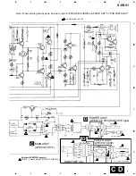
Page 9: ... F903 T1AL 250V F903 T2AL 250V RB901 RB902 RB903 RB903 RB906 RB905 CN901 T1 T1 22K 560 2W 47µF 35V MAIN ASSY APE0127C011 C POWER ASSY APE0141C003 MLXTW E type POWER ASSY APE0141C002 D D AC 220 230VÓ AC 110 120 127 220 240VÓ AUDIO SIGNAL ROUTE SDBXTW E type 1 5 7 3 6 2 8 4 L N L N SW902 Voltage Selector 110V 120 127V 220V 240VÓ Switches SDBXTW E type only ...

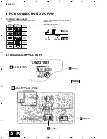
Page 10: ...several destinations For further information for respective destinations be sure to check with the schematic diagram 4 View point of PCB diagrams Symbol In PCB Diagrams Symbol In Schematic Diagrams Part Name B C E D D G G S S B C E B C E D G S B C E B C E B C E Transistor Transistor with resistor Field effect transistor Resistor array 3 terminal regulator Capacitor Connector P C Board Chip Part SI...

Page 11: ...S HS01 11 A B C D 1 2 3 4 1 2 3 4 D 4 2 POWER ASSY POWER ASSY D AC IN POWER SW T1 T1 POWER SW AC IN MLXTW E type SDBXTW E type ...

Page 12: ...12 A B C D 1 2 3 4 1 2 3 4 4 3 MAIN ASSY MAIN ASSY C T1 SP RB301 B RB502 B RB401 A SIDE A Q518 Q513 Q402 IC501 Q501 Q502 Q511 Q404 Q403 Q517 Q504 Q515 Q505 Q510 Q401 Q509 Q516 Q506 Q507 IC401 Q514 Q512 Q508 C ...

Page 13: ...art No LED ASSY APE0127C031 APE0127C031 JACK VOL ASSY APE0127C021 APE0127C021 MAIN ASSY APE0127C011 APE0127C011 POWER ASSY APE0141C003 APE0141C002 POWER Assy APE0141C003 and APE0141C002 are constructed the same except for the following NSP RB901 2P used unregistered part Not used NSP RB905 6P Not used used unregistered part Mark Remarks Symbol and Description Part No APE0141C003 APE0141C002 D Mark...

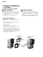
Page 14: ...e cover by unfastening the 4 screws attaching it Then remove the woofer by unfastening those screws When attaching it face its terminal rightward After attaching the woofer attach the rear plate cover by fastening 4 screws 2 REMOVING THE AMP ASSY 1 Remove the rear plate cover by unfastening 4 screws 1 attach ing it 2 Remove the woofer by unfastening 4 screws 2 attaching it Also disconnect the spea...

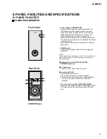
Page 15: ...al is received power automatically comes back on and the power indicator lights green 2POWER switch Pressing once switches the unit ON Press again to switch OFF NOTE If you are planning on switching the unit OFF for a long period of time make sure to check that the indicator light has gone out after switching OFF 3 3 3 3 3Voltage Selector VOLTAGE SELECTOR SDBXTW E type only 4 4 4 4 4AC power cord ...

Page 16: ...e 6 6 kg Power Amplifier Continous Power Output RMS 50 W 4 Ω 40 200 Hz Total Harmonic Distortion 0 5 40 200 Hz 4 Ω 12 5 W Input sensitivity at 100 Hz impedance LINE LEVEL RCA jack 160 mV 50 kΩ Speaker Enclosure Bass reflex floor standing type System 14 cm cone type 8 2 SPECIFICATIONS SDBXTW E type SDS1087 L 10m 2 Speaker Cords SDS1086 L 5m 2 RCA Plug Cord VRC0001 A06 L 3m 1 Non Slip Pads SEP1227 5...

Reviews: