background image

Summary of Contents for SA-610

Page 1: ...f f o ll r EefvicecVlanual S T E R E OA M P L I F I E R S Ci lO rrroruEErl ...

Page 2: ...5 B L O C K D I A G R A M 8 6 L E V E L D I A G R A M 8 T C T R C U I T D E S C R I P T I O N S 9 S A D J U S T M E N T S 1 0 9 E X P L O D E D V I E W S A N D P A R T S L I S T 1 1 10 SCHEMATIC DIAGRAM P C BOARD PATTERNSAND PARTS LIST 1 0 1M i s c e l l a n e a 1 4 10 2 Schematic Diagram 15 10 3 P C BoardConnection Diagram 18 10 4 PartsListof P C BoardAssembly 21 1 1 P A C K I N G 2 2 ...

Page 3: ... Level T A P E R E C l 2 1 5 0 m V S p e a k e r A B O F F siA ci1 cl Frequency Response PHONO RIAA Equalization TUNER AUX TAPE PLAY 20Hz to 20 000H210 3d8 1 2 1OHz to 60 000H2 13dB ToneControl B A S S t 1 0 d B 1 0 0 H 2 T R E B L E t 1 0 d B 1 0 0 0 0 H 2 Subsonic Filter 15Hz 6dB oct Loudness Contour Volumecontrolsetat 40dB position 6dB 100H2 3dB 10 000H2 HumandNoise lHF short circuited A networ...

Page 4: ...You can usethe treblecontrol to adjustthe soundin the high frequency range POWER METER This meter allowsyou to readout the ratedpowerlevel on the fluorescentdisplay tube when speakers with a nominal impedanceof 8 ohms are connectedto the ampl ifier sspeaker terminals FUNCTTON INDICATORS The TUNER PHONO TAPE AUX functionindicators light up in accordance with the positionof the function se lector FU...

Page 5: ...nocar tridge and speaker tone quality and listening room acoustics powentNDtcAToR When the power switch is setto ON this lamp lightsup indicating theamplif ieristurnedon sA Ci1cl LouolrrEss swtrcH Whenlistening to a performance with the volumecontrol turned down set this switch to ON and the bassand treblewill beaccentuated Whenthe volumeis low the humanear finds it harder to hearthe bassand trebl...

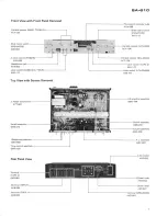
Page 6: ...x screwsO o The i marh found on some component parts indicates the importance of the safety factor of the part There fore when replacing be sure to use parts of identical designation 4 PARTS LOCATION FrontPanelView m t J g r Knob BALANCEI AAB 223 Leverknob LOUDNESS TAPE2 AAD 2OO o oo o Bonnet case Front panel 6 ...

Page 7: ...View Terminal INPUT AK8 064 Terminal TAPE 1 AKB 063 tlr rl r l tu I Variableresistor BA LANCE ACT 130 Lever switch TAPE2 siA 610 Fluorescentindicator tube AAV O06 Slide rotary switch F U N C T I O N A S X I1 3 I o L Variable resistor VOLUME A S K 1 7 2 Leverswitch LOUDN ESS A S K 1 7 1 AF amplifierassembly GWK 144 Switch assembly GWS 216 Volume assembly GWX459 I AC socker AKP O32 1i Power code ADG...

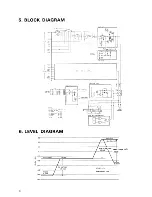
Page 8: ...CK DIAGRAM swtrcHEs st Fu trox luxEP M raPEI AUX 32 fAPE ON 6F t3 ouoi ls ox gll 54 Su6oirt t5Hrl Ox 6 55 SPEAXERS O F A s6 s R ox Il se ioilE or _lI 6 LEVELDIAGRAM l tlJ roo t xeai pnone eo AUX TUNER 15OmV ...

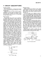
Page 9: ... the high end frequency responsedeterioration The power amplifier stage is a complementary 2 stage Darlington connection resulting in an output power rating of 45W 45W 8Q 20Hz 2OkHz harmonic distortion of less than O O37o 20H2 20kHz at rated output and output power bandwidth of 5Hz 50kHz 0 O3 THD Certainly a superb performance for an amplifier of this classis obtained Constant current circuit to o...

Page 10: ...s lessthan 4mV cut jumper wire A Lch and jumper wire B Rch If the voltage exceeds70mV check for circuit failure 8 2 OUTPUT INDICATOR ADJUSTMENT 1 Set the TONE CONTROL to the center position 2 Set the SPEAKERS selector to the A position and connect an 8O resistorand AC voltmeter to the speaker output terminals 3 Set the FUNCTION switch to the AUX position and apply a 7kHz 150mV signal to the AUX te...

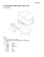
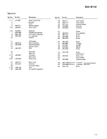
Page 11: ...onent parts indicates the importance of the safety factor of the part Therefore when replacing be sure to useparts of id enti cal designation Key No Part No Description f 1 2 3 4 5 6 7 8 9 10 ANE 269 ABA 079 AAD 2OO AN8 847 AAB 222 AAB 223 AAB 221 ABA 186 AB4 066 Bonnet case Screw Lever knob Front panel assembly Knob Knob Knob Screw Bottom plate Screw 4 t4 1 r ...

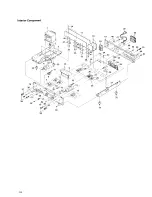
Page 12: ...InteriorComponent l K um l _ s il Y 2o 44 29 30 32 34 36 2ssl ffu Q N f ro 9 i w 38 ...

Page 13: ...ume assembly Cushion rubber LED Panel stay Heat sink AC socket Rear panel Power code Strein relief Terminal Terminal GND Fuse AF amplifier assembly 26 ASK I71 27 ASK 172 28 ACT 130 29 AKB 063 30 AKB 064 3 1 32 AEC 672 33 ABA 107 34 484 066 35 ABA 234 36 A84 026 37 M45 O86 38 871 004 39 ABE 005 40 ABA 240 4 t ABA 198 42 43 AEC 352 44 45 AEC 488 46 2SA1108 A Oor R 47 25C2588 A OorR 48 ABA 145 Lever ...

Page 14: ...cing be sure to use parts of identical designation Miscellaneous Parts ASSEMBLIES Part No Symbol Description GWK 144 AF amplifier assembly GWG 138 Tone control assembly GWS 215 Switch assembly GWS 216 Switch assembly GWX459 Volume assembly GWX460 Headphonesassembly AWV 007 F L assembly SEMICONDUCTORS Part No Symbol Description OTHERS Part No Symbol Description A 4TT 667 T1 Powertransformer 7 ner t...

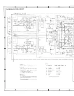
Page 15: ... ffii l l l iHEi Tf llll l _H ll l l llll 1 ffiNrRoLAss v 2 2 G I i t 41 t_ dr f u 1 oI Hlfd h l J L i HE l ftzzzu l l r Ll r I I I I I I L SWITCHES s t 7 F U N C T I O N T U N E R P H O N O T A P E I A U X S Z T A p E O N O F F 5 3 L O U D N E S S O N O F F 5 4 S U B S O N I C 1 5 H z O N O F F 5 5 S P E A K E R S O F F A B 5 6 P O W E R O N _ O F F 5 8 T O N E O N O F F The underlinedindicates t...

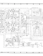
Page 16: ... I _ J rJ d L Ass y 2 21 GWG 138 I 8 20 t 2 w I a s E o o 3 t 2SC19r4A G ol 82P ts2076 c6l roo so Q 2 H A r 2 0 t O J r 3i R92 ilOk R52 R z O l g k R z Z t O C 4 8 az6 2scrass R ro A I orrcezso 0 l P O W E R A I C 5 8 4A O OllACtso T 2 ATT 5 77 ot7 lt zwl A rro oizso v r a A v o o 6 AF AMP Ass y 2 21 G W K 1 4 4 A C P OWE R C O R O a D G o 2 3 A I cez 6 ot t L _ _ _ a c r 2 5 J ...

Page 17: ... il o 4 L g_l I R I 2k I I l i l l l t i 2SA985 2SC 2275 trr 7 of Transistors and fCs 2 S C 1 8 1 5 A 2 S C 1 9 1 4 4 suffix O otNo B ilf rvpe No n E h 1tt ve l 2SC nlg 2SC 2602 LotNo S a n LfT rvpe No flK s B 3r 2SA1108A 2SC2588A Type __N _ n ffi ll lt J Lot No s u l l u s 2SC138 n ii r ot ruo Ul rvpe No m 2sc r r p LotNo ryperuo t hre fr1 c i il il u surTrx I EU 2 S D 7 1 2 fr ru fu LotNoffin uu...

Page 18: ...10 3P C BOARDCONNECTION DIAGRAM FL Asr y AWV 007I Lch Rch HEADPHONE Arr y GWX460I SWITCH As y cws 216 ...

Page 19: ...EtA Ci1 cl HEADPHONE As y cwx460l VOLUME Arr y GWX459 2sA11o AlA ...

Page 20: ...I l o ACl 20V 6OHz t t L _ _ J T 1 POWER TFIANSFORMER S W I T C H E O U N S W I T C H E O AF AMPAr y GWK 1441 CONTROL Ar y GWG I38 ...

Page 21: ...01I 012 013 014 026 015 016l hfeshoutdhavethe 017 018 J same rank o23 O24 o2s o27 Dl D4 Dl8 D5 D6 D7 D8 D9 DlO D 1 1 D 1 4 D l 5 D 1 6 D17 c t c2 c54 c59 c60 c61 css c56 C77 c83 C84 c49 c51 c 1 8 C 1 7 c33 C34 c71 c72 c25 C26 c3 c4 c75 C76 c19 C20 c37 C38 c41 C42 c7 c8 c86 C87 c5 c6 c21 22 C29 C32 c15 C16 C27 C2A C88 C85 c35 C36 c43 C46 c50 c39 C40 c47 C48 c78 C81 c11 C12 c9 cl0 c23 C24 c13 C l4 c...

Page 22: ...Description ASX 1 3 56 Slide rotary switch FUNCTION PartsListof VolumeAssembly GWX 4S9 Part No Symbol Description ACV 184 VR2 Variable resistor VOLUME PartsListof Headphones Assembly GWX 460 Part No Symbol Description AKN 023 Headphonesjack coMA 303J 50 coMA 124K50 cosA 270KsO CQMA 122K50 coMA 562K50 Note RESISTORS Part No ACT 127 RDT4PMD tr qJ PartsListof Switch Part No ASE OO3 R SlP331J RDlzrPM ...

Page 23: ...ECTFICDNICE CCIFIPCIF ATICIN E 5 Oxfond Dnive Moon chie New Jereey O7O7 U S A FGIilCEFI eECTFlClillC El rFlCtFE N Luithagen Heven 9 2O3O Antwe p Elelgium FCIwCEF El CTFlCtI llC l A J3TFIALIA FTY LtEl 17A 1A4 Eloundenv F oad Eltreeside Victonia 3 l 95 Augtnelie aRT 478 E A i T a 7 q P F h t e d i n J e o a n ...

Reviews: