background image

Installation

Installation

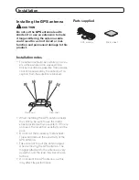
Installing the GPS antenna 

 CAUTION 

Do not cut the GPS antenna lead to 

shorten it or use an extension to make 

it longer. Altering the antenna cable 

could result in a short circuit or mal-

function and permanent damage to this 

product.


Installation notes 

• 

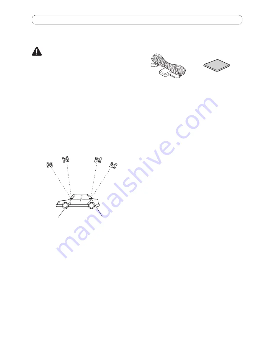
The antenna should be installed on a lev-

el surface where radio waves will be 

blocked as little as possible. Radio waves 

cannot be received by the antenna if re-

ception from the satellite is blocked. 

Dashboard

Rear shelf

• 

When installing the GPS antenna inside 

the vehicle, be sure to use the metal 

sheet provided with your system. If this is 

not used, the reception sensitivity will be 

poor.

• 

Do not cut the accessory metal sheet. 

This would reduce the sensitivity of the 

GPS antenna.

• 

Take care not to pull the antenna lead 

when removing the GPS antenna. The 

magnet attached to the antenna is very 

powerful, and the lead may become de-

tached.

• 

Do not paint the GPS antenna, as this 

may affect its performance.

Parts supplied 

GPS antenna

Metal sheet 

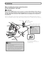
When installing the antenna inside the vehicle  

(on the dashboard or rear shelf) 

 WARNING

Do not install the GPS antenna over any sensors or vents on the dashboard of the vehicle, as 
doing so may interfere with the proper


functioning of such sensors or vents and may compro-

mise the ability of the metal sheet under the GPS antenna to properly and securely affix to 

Affix the metal sheet on the surface as level as possible where the GPS antenna faces the win-
dow. Place the GPS antenna on the metal sheet. (The GPS antenna is fastened with its magnet.) 

GPS antenna

Metal sheet 
Peel off the protective 
sheet on the rear.

Make sure the surface is free of 
moisture, dust, grime, oil, etc., 
before affixing the metal sheet.

Clamps
Use separately sold clamps
to secure the lead where necessary
inside the vehicle.

 Note

The metal sheet 

contains a strong 

adhesive which may 

leave a mark on the 

surface if it is removed.

When attaching the metal sheet, do not cut 

it into small pieces.

• 

Some vehicles use window glass that does 

not allow signals from GPS satellites to pass 

through. On such models, install the GPS 

antenna on the outside of the vehicle.


Summary of Contents for SPH-DA210

Page 1: ...SPH DA210 SPH DA110 AppRadio Installation Manual ...

Page 2: ...g column or shift lever Be sure to install this product its cables and wiring away in such so that they will not obstruct or hinder driving Make sure that the cables and wires will not interfere with or become caught in any of the vehicle s moving parts especially the steering wheel shift lever parking brake sliding seat tracks doors or any of the vehicle s controls Do not route wires where they w...

Page 3: ...itch ACC O N S T A R T O F F O N S T A R T O F F ACC position No ACC position To avoid short circuiting cover the dis connected lead with insulating tape It is especially important to insulate all un used speaker leads which if left uncov ered may cause a short circuit Refer to the owner s manual for details on connecting the power amp and other units then make connections according ly Since a uni...

Page 4: ...holder into the groove of this prod uct Tab Groove 2 Insert the two upper tabs into the this product by pushing the HDMI ca ble holder Tabs p Use the HDMI cable holder when you con nect this product with the separately sold HDMI USB interface cable for iPod iPhone CD IH202 or App Connectivity Kit CD AH200 p Never grip the holder tightly or use force when removing or attaching ...

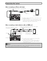
Page 5: ...e with Lightning connector HDMI cable holder HDMI port Notes When you connect the High Speed HDMI Cable use the HDMI cable holder to fix it securely The constant connection of the separately sold Lightning Digital AV Adapter Apple Inc products is not guaranteed Disconnect it when it is not used as with a mobile device Lightning Digital AV Adapter Apple Inc products sold separately High Speed HDMI ...

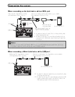
Page 6: ...able HDMI port 5 For details concerning operations and compatibility refer to the Operation Manual 6 For details about how to connect the separately sold App Connectivity Kit CD AH200 refer to the App Connectivity Kit manual HDMI cable holder Android device 5 Adapter cable 6 HDMI Type A D sold separately High Speed HDMI Cable 6 Type A A sold separately USB cable 6 Type USB A USB A sold separately ...

Page 7: ...ix it securely An adapter cable will not be used if you use the MHL adapter USB cable 8 Type USB A USB A sold separately 0 75 m 2 ft 6 in USB micro USB cable 8 Type USB A micro USB B sold separately 1 5 m 4 ft 11 in USB cable When connecting a MirrorLink device with a USB port MirrorLink device 9 USB cable USB cable 10 Type USB A USB A sold separately 0 75 m 2 ft 6 in USB micro USB cable 10 Type U...

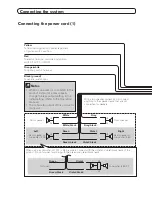
Page 8: ...V DC ON OFF Orange white To lighting switch terminal Black ground To vehicle metal body With a two speaker system do not connect anything to the speaker leads that are not connected to speakers Front speaker White White black Gray Gray black Front speaker Left Rear speaker or subwoofer 4 Ω Green Green black Violet Violet black Right When using a subwoofer of 70 W 2 Ω be sure to connect with the vi...

Page 9: ...ing the system 10 This product Fuse 10 A Power cord Blue white To auto antenna relay control terminal If the vehicle has a glass antenna connect to the antenna booster power control terminal max 300 mA 12 V DC ...

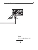
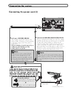
Page 10: ...RNING LIGHT GREEN LEAD AT POWER CONNECTOR IS DESIGNED TO DETECT PARKED STATUS AND MUST BE CONNECTED TO THE POWER SUPPLY SIDE OF THE PARKING BRAKE SWITCH IMPROPER CONNECTION OR USE OF THIS LEAD MAY VIOLATE APPLICABLE LAW AND MAY RESULT IN SERIOUS INJURY OR DAMAGE Note When you use a rear view camera please make sure to connect this lead Otherwise you cannot switch to the rear view camera picture Po...

Page 11: ...old separately Power amp sold separately Power amp sold separately System remote control Left Right Front speaker Front speaker Subwoofer or Rear speaker Subwoofer or Rear speaker Blue white To system control terminal of the power amp max 300 mA 12 V DC Note You can change the RCA output of the subwoofer depending on your subwoofer system Refer to the Operation Manual ...

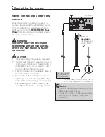
Page 12: ...ers or backing into a tight parking spot Do not use this func tion for entertainment purposes Objects in rear view may appear closer or more distant than in reality Please note that the image area shown by the rear view camera may differ slight ly when full screen images are displayed when backing and when checking the rear of the vehicle while moving forward This product Rear view camera e g ND B...

Page 13: ...esulting in a short circuit Please confirm the proper function of your vehicle s other equipment after installation of this product Do not install this product where it may i obstruct the driver s vision ii impair the performance of any of the vehicle s operating systems or safety features including airbags hazard lamp buttons or iii impair the driver s ability to safely operate the vehicle Instal...

Page 14: ...rely If this product is not securely installed the cur rent location of the vehicle cannot be dis played correctly Install this product horizontally on a sur face within 0 to 60 degrees tolerance Im proper installation of the unit with the surface tilted more than these toleranc es increases the potential for errors in the vehicle s location display and might otherwise cause reduced display perfor...

Page 15: ...ew holes are aligned with the screw holes of the brack et and tighten the screws at three or four lo cations on each side Use either the truss head screws 5 mm 8 mm or flush surface screws 5 mm 9 mm depending on the shape of the bracket s screw holes If the tab interferes with installation you may bend it down out of the way Factory radio mounting bracket Truss head screw or flush surface screw Be...

Page 16: ...ived by the antenna if re ception from the satellite is blocked Dashboard Rear shelf When installing the GPS antenna inside the vehicle be sure to use the metal sheet provided with your system If this is not used the reception sensitivity will be poor Do not cut the accessory metal sheet This would reduce the sensitivity of the GPS antenna Take care not to pull the antenna lead when removing the G...

Page 17: ...e win dow Place the GPS antenna on the metal sheet The GPS antenna is fastened with its magnet GPS antenna Metal sheet Peel off the protective sheet on the rear Make sure the surface is free of moisture dust grime oil etc before affixing the metal sheet Clamps Use separately sold clamps to secure the lead where necessary inside the vehicle Note The metal sheet contains a strong adhesive which may ...

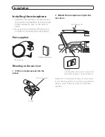
Page 18: ...hone Parts supplied Microphone Double sided tape Mounting on the sun visor 1 Fit the microphone lead into the groove Groove Microphone lead 2 Attach the microphone clip to the sun visor Microphone clip Clamps Use separately sold clamps to secure the lead where necessary inside the vehicle Install the microphone on the sun visor when it is in the up position It cannot recognize the driver s voice i...

Page 19: ...rophone clip Microphone base Tab 2 Mount the microphone on the steering column Double sided tape Install the microphone on the steering column keeping it away from the steering wheel Clamps Use separately sold clamps to secure the lead where necessary inside the vehicle Adjusting the microphone angle The microphone angle can be adjusted PIONEER AUDIO SYSTEMS CAR STEREOS ...

Reviews: