22
CDJ-350
1
2
3
4
A
B
C
D
E
F
1
2
3
4
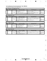
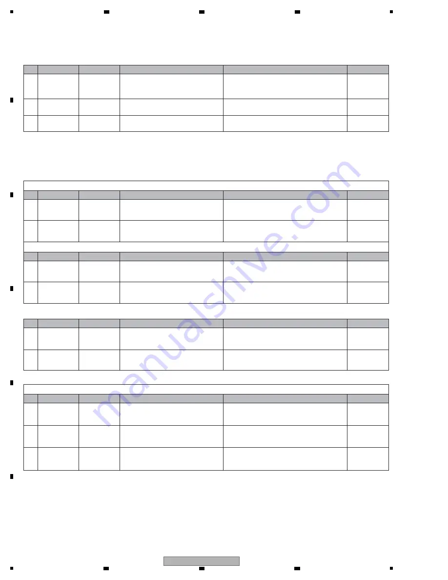
[2-2] The LED does not light.
—
—
—
[3] Operations (Keys/variable controls/JOG)
As operations of all keys, variable controls, and JOG dial can be checked in Service mode.
[3-1] No key functions
STA
N
DBY, USB STOP, PLAY, CUE, LOOP I
N
/OUT, RELOOP, LOOP DI
V
IDE+, or LOOP DI
V
IDE- key does not function.
1
Loose connection
/Defective SW
Related point
Check if there is loose connection on the
signal line from the PA
N
EL CPU (IC501)
up to the SW.
If there is no loose connection and if the signal does
not become "L" when the SW is pressed, that SW is
defective.
2
Defective PA
N
EL
CPU (IC501)
P
N
LB Assy
If the symptom persists after the above
corrections,
Check a mounting state of PA
N
EL CPU(IC501).
If the mounting is OK, the PA
N
EL CPU may be
defective.
The signals from other keys are analog and connected to multiple switches.
1
Loose connection
/Defective SW
Related point
Check if there is loose connection on the
signal line from the PA
N
EL CPU (IC501)
up to the SW.
If the SWs connected to the signal line function
properly and if the connections are properly made,
the SWs may be defective.
2
Defective PA
N
EL
CPU (IC501)
P
N
LB Assy
If the symptom persists after the above
corrections,
Check a mounting state of PA
N
EL CPU(IC501).
If the mounting is OK, the PA
N
EL CPU may be
defective.
[3-2] Rotary selector not controllable
1
Defective rotary
selector
P
N
LB Assy
Check if the signals from the RE
N
C_1, RE
N
C
_2, and RE
N
C_SW signal lines are normal
when the rotary selector is turned or pressed.
If the signals are not normal, check the connections of
the signal lines. If the connections are properly made,
the encoder (S527) may be defective. Replace it.
2
Defective PA
N
EL
CPU (IC501)
P
N
LB Assy
If the symptom persists after the above
corrections,
Check a mounting state of PA
N
EL CPU(IC501).
If the mounting is OK, the PA
N
EL CPU may be
defective.
[3-3] Variable controls not controllable
Tempo slider not controllable
1
Loose
connection
P
N
LB Assy
Check if there is loose connection on the
signal line from the PA
N
EL CPU (IC501)
to the tempo slider (
V
R501).
If the connections of signal line are improper,
resolder it.
2
Defective tempo
slider
P
N
LB Assy
Check the TEMPO signal level.
If the voltage of the TEMPO signal line (IC501-pin 97)
does not change between 5.0
V
and 0
V
, the tempo
slider may be defective.
3
Defective PA
N
EL
CPU (IC501)
P
N
LB Assy
If the symptom persists after the above
corrections,
Check a mounting state of PA
N
EL CPU(IC501).
If the mounting is OK, the IC501 may be damaged.
[9] Basic operation
check of CPU/DSP
[9] Basic operation
check of CPU/DSP
—
—
—
—
[9] Basic operation
check of CPU/DSP
[9] Basic operation
check of CPU/DSP
[9] Basic operation
check of CPU/DSP
No.
Cause
Diagnostics Point
Item to be Checked
Corrective Action
Reference
No.
Cause
Diagnostics Point
Item to be Checked
Corrective Action
Reference
No.
Cause
Diagnostics Point
Item to be Checked
Corrective Action
Reference
No.
Cause
Diagnostics Point
Item to be Checked
Corrective Action
Reference
No.
Cause
Diagnostics Point
Item to be Checked
Corrective Action
Reference
1
Signal errors
P
N
LB Assy
Check that the control signal for the LED
is output from the PA
N
EL CPU (IC501).
If no signal is output, check a mounting state of
PA
N
EL CPU(IC501). If the mounting is OK, the
IC501 may be defective.
2
Defective parts
of LED
P
N
LB Assy
Check that the forward voltage (2.2 - 2.7
V
)
is present at both ends of the LED.
If the forward voltage is not present, then the LED
itself is defective.
3
Defective parts
of transistor
P
N
LB Assy
If the symptom persists after the above
corrections,
The transistor may be defective.
Summary of Contents for TRAKTOR PRO CDJ-350
Page 8: ...8 CDJ 350 1 2 3 4 A B C D E F 1 2 3 4 2 2 USABLE DISCS AND USB DEVICES ...
Page 9: ...9 CDJ 350 5 6 7 8 5 6 7 8 A B C D E F ...
Page 10: ...10 CDJ 350 1 2 3 4 A B C D E F 1 2 3 4 2 3 PANEL FACILITIES ...
Page 11: ...11 CDJ 350 5 6 7 8 5 6 7 8 A B C D E F ...
Page 71: ...71 CDJ 350 5 6 7 8 5 6 7 8 A B C D E F ...
Page 73: ...73 CDJ 350 5 6 7 8 5 6 7 8 A B C D E F H C 4 4 CN401 ...
Page 75: ...75 CDJ 350 5 6 7 8 5 6 7 8 A B C D E F H C 4 4 CN401 ...
Page 79: ...79 CDJ 350 5 6 7 8 5 6 7 8 A B C D E F ...
Page 93: ...93 CDJ 350 5 6 7 8 5 6 7 8 A B C D E F H H SMPS ASSY SIDE B SIDE B CN1 CN2 FOR CUXJ ...


