41
VSX-519V-K
5
6
7
8
5
6
7
8
A
B
C
D
E
F
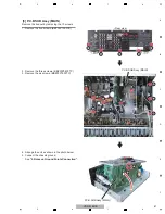
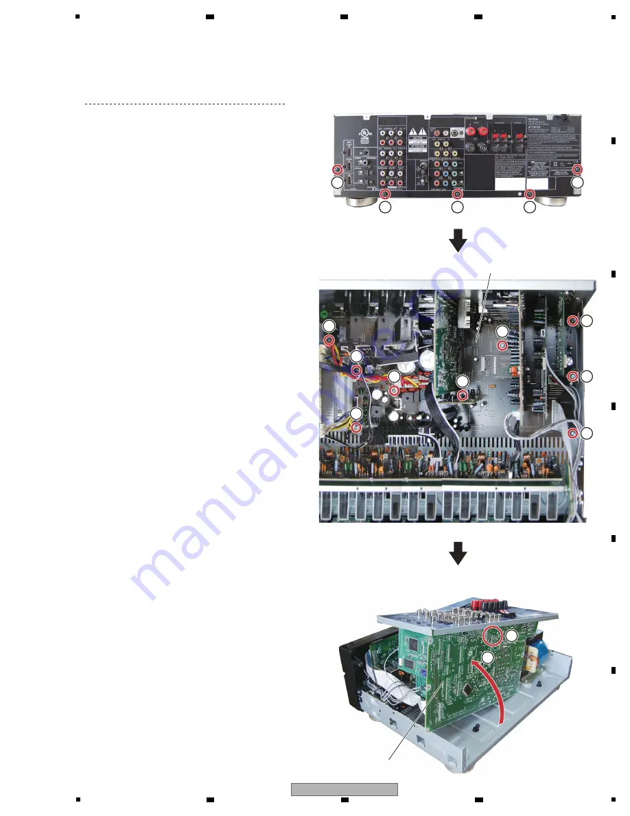
[3] P.C.B SUB Assy (MAIN)
Remove the bonnet by removing the 10 screws.
1. Remove the five screws. (BBT30P100FTB)
1
1
1
1
1
2
3
3
3
3
3
3
2
2
• Rear view
2. Remove the three screws. (BBZ30P080FTC)
3. Remove the six screws. (BBZ30P180FTC)
4. Arrange the unit as shown in the photo below.
5. Connect the chassis ground.
See
“2. Notes on Ground Points Connection”.
P.C.B SUB Assy (MAIN)
P.C.B SUB Assy (MAIN)
4
5
Summary of Contents for VSX-519V-K
Page 18: ...18 VSX 519V K 1 2 3 4 A B C D E F 1 2 3 4 4 3 VIDEO BLOCK DIAGRAM P C B SUB ASSY VIDEO 519 L ...
Page 19: ...19 VSX 519V K 5 6 7 8 5 6 7 8 A B C D E F 4 4 U COM BLOCK DIAGRAM P C B SUB ASSY FRONT C ...
Page 45: ...45 VSX 519V K 5 6 7 8 5 6 7 8 A B C D E F ...
Page 57: ...57 VSX 519V K 5 6 7 8 5 6 7 8 A B C D E F J CN401 M CP107 A FL FL FL SL SL SL C C C ...
Page 67: ...67 VSX 519V K 5 6 7 8 5 6 7 8 A B C D E F P 2 2 116 ...
Page 71: ...71 VSX 519V K 5 6 7 8 5 6 7 8 A B C D E F B A SIDE B B P C B SUB ASSY P T ...
Page 77: ...77 VSX 519V K 5 6 7 8 5 6 7 8 A B C D E F J 01 SIDE A SIDE B ...
Page 81: ...81 VSX 519V K 5 6 7 8 5 6 7 8 A B C D E F L SIDE A ...
Page 83: ...83 VSX 519V K 5 6 7 8 5 6 7 8 A B C D E F L SIDE B ...
Page 89: ...89 VSX 519V K 5 6 7 8 5 6 7 8 A B C D E F P N SIDE B ...

