33
VSX-819H-K
5
6
7
8
5
6
7
8
A
B
C
D
E
F
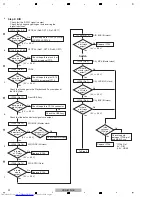
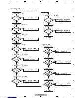
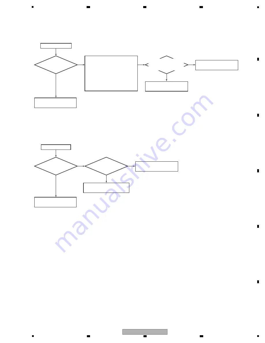
Step 3: Operation of iPod (Authentication process)
Do
SCL and SDA
communicate?
Yes
N
o
N
o
IC
8
04 (pins 12, 13) SCL, SDA (I2C between IC
8
01 and IC
8
04)
Does RESET_AUTH
(pin 4) reset it?
High after the reset
Replace IC
8
04.
W
hen SCL and SDA are
normal operation = High (3.3
V
).
Connect iPod, and communicate
it about 10 seconds later
(authentication starts).
And communicate it about 60
seconds later (authentication is
complete).
Check the path between
IC
8
01 (pin 120).
N
o
Yes
Step 4 Audio Out check
Is there
a S/PDIF
signal
?
Replace IC
8
01.
Yes
N
o
C
N8
05 (pin 1)
S/PDIF output
Check the
path between IC
8
01
(pin 105)
Check the parts and pattern
C
N8
05 and IC
8
01.
Yes
N
o
Operation of IC
8
04 is OK.
To STEP 4
Refer to the DSP Assy
troubleshooting.
Summary of Contents for VSX-819H-K - AV Receiver - Gloss
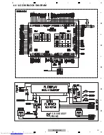
Page 19: ...19 VSX 819H K 5 6 7 8 5 6 7 8 A B C D E F 4 4 U COM BLOCK DIAGRAM P C B SUB ASSY FRONT C ...
Page 49: ...49 VSX 819H K 5 6 7 8 5 6 7 8 A B C D E F ...
Page 55: ...55 VSX 819H K 5 6 7 8 5 6 7 8 A B C D E F ...
Page 61: ...61 VSX 819H K 5 6 7 8 5 6 7 8 A B C D E F J CN401 M CP107 A FL FL FL SL SL SL C C C ...
Page 71: ...71 VSX 819H K 5 6 7 8 5 6 7 8 A B C D E F P 2 2 CN805 R 116 ...
Page 73: ...73 VSX 819H K 5 6 7 8 5 6 7 8 A B C D E F R CP105 A CP705 C ...
Page 77: ...77 VSX 819H K 5 6 7 8 5 6 7 8 A B C D E F B A SIDE B B P C B SUB ASSY P T ...
Page 83: ...83 VSX 819H K 5 6 7 8 5 6 7 8 A B C D E F J 01 SIDE A SIDE B ...
Page 87: ...87 VSX 819H K 5 6 7 8 5 6 7 8 A B C D E F L SIDE A ...
Page 89: ...89 VSX 819H K 5 6 7 8 5 6 7 8 A B C D E F L SIDE B ...
Page 95: ...95 VSX 819H K 5 6 7 8 5 6 7 8 A B C D E F P N SIDE B ...

