39
VSX-819H-K
5
6
7
8
5
6
7
8
A
B
C
D
E
F
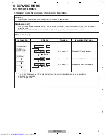
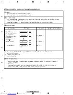
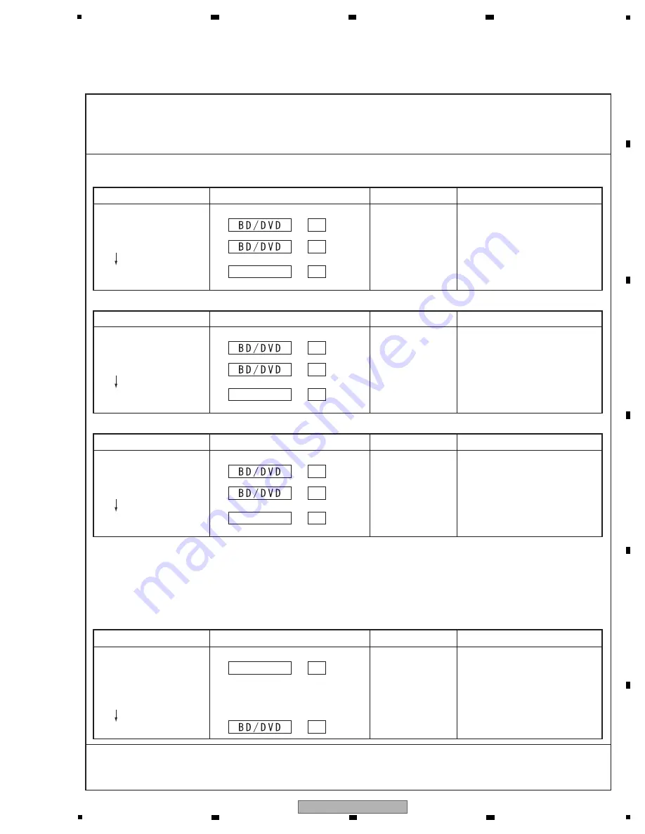
[3] The unit’s operation when a error is detected
[Purpose]
[Basic operations]
FL Display
Description of Indications
Key Operation
3.1 DC (AMP is abnormality) error detection
(
N
ormal display)
(DC detection)
(Auto)
(RECEI
V
ER PO
W
ER OFF)
usually
*1, *2
N
ormal display
Time (sec.)
• The unit’s operation when a DC/O
V
ER/TEMP error is detected is described here.
• How to cancel the status after detection of a DC error is described here, because no key input will be
accepted after a DC error detection.
*1 The time required for the unit to be shut off after an error is detected depends on the circuit configuration.
*2 If the unit is automatically shut off after a DC error is detected, no key input will be accepted afterward.
(The power will not be turned O
N
.)
To turn it on again, see “3.4 How to cancel the status after detection of a DC error” below.
A key input will not be inhibited after an O
V
ERLOAD/TEMP error is detected. (The unit can be turned O
N
.)
Simultaneously holding the [AD
V
A
N
CD SURROU
N
D] and [STA
N
DBY/O
N
] keys on the
front panel pressed for 2 seconds will cancel Key Input Inhibition mode after a DC error
detection and turn the unit O
N
.
[Detailed explanations]
FL Display
Description of Indications
Key Operation
3.2 OVERLOAD (overcurrent) error detection
(
N
ormal display)
(O
V
ERLOAD detection)
(Auto)
(RECEI
V
ER PO
W
ER OFF)
usually
*1
N
ormal display
Time (sec.)
FL Display
Description of Indications
Key Operation
3.3 TEMP (AMP overheat) error detection
(
N
ormal display)
(TEMP detection)
(Auto)
(RECEI
V
ER PO
W
ER OFF)
usually
*1
N
ormal display
Time (sec.)
FL Display
Description of Indications
Key Operation
3.4 How to cancel the status after detection of the DC error
(STA
N
DBY state)
(
N
ormal display)
usually
N
ormal display
Time (sec.)
[AD
V
A
N
CED SURROU
N
D]
+ [STA
N
DBY/O
N
]
(press and hold the keys
for 2 seconds.)
Summary of Contents for VSX-819H-K - AV Receiver - Gloss
Page 19: ...19 VSX 819H K 5 6 7 8 5 6 7 8 A B C D E F 4 4 U COM BLOCK DIAGRAM P C B SUB ASSY FRONT C ...
Page 49: ...49 VSX 819H K 5 6 7 8 5 6 7 8 A B C D E F ...
Page 55: ...55 VSX 819H K 5 6 7 8 5 6 7 8 A B C D E F ...
Page 61: ...61 VSX 819H K 5 6 7 8 5 6 7 8 A B C D E F J CN401 M CP107 A FL FL FL SL SL SL C C C ...
Page 71: ...71 VSX 819H K 5 6 7 8 5 6 7 8 A B C D E F P 2 2 CN805 R 116 ...
Page 73: ...73 VSX 819H K 5 6 7 8 5 6 7 8 A B C D E F R CP105 A CP705 C ...
Page 77: ...77 VSX 819H K 5 6 7 8 5 6 7 8 A B C D E F B A SIDE B B P C B SUB ASSY P T ...
Page 83: ...83 VSX 819H K 5 6 7 8 5 6 7 8 A B C D E F J 01 SIDE A SIDE B ...
Page 87: ...87 VSX 819H K 5 6 7 8 5 6 7 8 A B C D E F L SIDE A ...
Page 89: ...89 VSX 819H K 5 6 7 8 5 6 7 8 A B C D E F L SIDE B ...
Page 95: ...95 VSX 819H K 5 6 7 8 5 6 7 8 A B C D E F P N SIDE B ...


