41
VSX-819H-K
5
6
7
8
5
6
7
8
A
B
C
D
E
F
2. Notes on Ground Points Connection
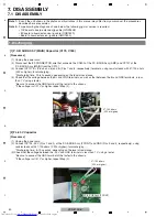
When reassembling after disassembling the product for repair, before connecting the power cord, make sure that the 2P
wire from the CN206 of the P.C.B SUB Assy (DSP) is connected to the CP803 of the P.C.B TOTAL Assy (INPUT).
If the power is turned ON without the above connection, the CODEC IC (IC109: AK4588) of the P.C.B SUB Assy
(DSP) may be damaged.
[Note 1]
During repair, before checking the P.C.B SUB Assy (MAIN), etc., with the rear chassis removed, be sure to connect the
GND terminal of the main capacitor to the rear chassis (TUNER PACK CHASSIS), as shown below, then connect the
power cord.
Without grounding connection, the protection circuit will be activated.
After repairing, be sure to remove the ground wire before reassembling.
[Note 2]
CP803
TUNER PACK CHASSIS
P.C.B SUB Assy (MAIN)
MAIN CAPAITOR GND
REAR CHASSIS
REAR CHASSIS
GND WIRE
(Be sure to disconnect the GND
wire before reassembly.)
Summary of Contents for VSX-819H-K - AV Receiver - Gloss
Page 19: ...19 VSX 819H K 5 6 7 8 5 6 7 8 A B C D E F 4 4 U COM BLOCK DIAGRAM P C B SUB ASSY FRONT C ...
Page 49: ...49 VSX 819H K 5 6 7 8 5 6 7 8 A B C D E F ...
Page 55: ...55 VSX 819H K 5 6 7 8 5 6 7 8 A B C D E F ...
Page 61: ...61 VSX 819H K 5 6 7 8 5 6 7 8 A B C D E F J CN401 M CP107 A FL FL FL SL SL SL C C C ...
Page 71: ...71 VSX 819H K 5 6 7 8 5 6 7 8 A B C D E F P 2 2 CN805 R 116 ...
Page 73: ...73 VSX 819H K 5 6 7 8 5 6 7 8 A B C D E F R CP105 A CP705 C ...
Page 77: ...77 VSX 819H K 5 6 7 8 5 6 7 8 A B C D E F B A SIDE B B P C B SUB ASSY P T ...
Page 83: ...83 VSX 819H K 5 6 7 8 5 6 7 8 A B C D E F J 01 SIDE A SIDE B ...
Page 87: ...87 VSX 819H K 5 6 7 8 5 6 7 8 A B C D E F L SIDE A ...
Page 89: ...89 VSX 819H K 5 6 7 8 5 6 7 8 A B C D E F L SIDE B ...
Page 95: ...95 VSX 819H K 5 6 7 8 5 6 7 8 A B C D E F P N SIDE B ...

