<KMIZX> <06C00000>
XDV-P6
Printed in Japan
Imprimé au Japon
<CRD4109-A> UC
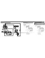
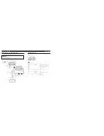
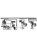
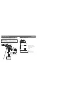
Connecting the Units
<ENGLISH>
This product conforms to CEMA cord colors.
Le code de couleur des câbles utilisé pour ce produit est
conforme à CEMA.
INST
ALLA
TION MANUAL
MANUEL D’INST
ALLA
TION
WARNING:
• To avoid the risk of accident and the
potential violation of applicable laws, the
front DVD or TV (sold separately) fea-
ture should never be used while the vehi-
cle is being driven. Also, Rear Displays
should not be in a location where it is a
visible distraction to the driver.
• In some countries or states the viewing of
images on a display inside a vehicle even
by persons other than the driver may be
illegal. Where such regulations apply,
they must be obeyed and this unit’s DVD
features should not be used.
CAUTION:
• PIONEER does not recommend that you
install or service your display (sold sepa-
rately) yourself. Installing or servicing
the product may expose you to risk of
electric shock or other hazards. Refer all
installation and servicing of your display
to authorized Pioneer service personnel.
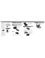
• Secure all wiring with cable clamps or
electrical tape. Do not allow any bare
wiring to remain exposed.
• Do not drill a hole into the engine com-
partment to connect the yellow lead of
the unit to the vehicle battery. Engine
vibration may eventually cause the insu-
lation to fail at the point where the wire
passes from the passenger compartment
into the engine compartment. Take extra
care in securing the wire at this point.
• It is extremely dangerous to allow the
display (sold separately) lead to become
wound around the steering column or
gearshift. Be sure to install the display in
such a way that it will not obstruct dri-
ving.
• Make sure that wires will not interfere
with moving parts of the vehicle, such as
the gearshift, parking brake or seat slid-
ing mechanism.
• Do not shorten any leads. If you do, the
protection circuit may fail to work prop-
erly.
• Do not install the display (sold sepa-
rately) where it may (i) obstruct the
driver’s vision, (ii) impair the perfor-
mance of any of the vehicle’s operat-
ing systems or safety features, includ-
ing air bags, hazard lamp buttons or
(iii) impair the driver’s ability to
safely operate the vehicle.
Note:
• This unit is for vehicles with a 12-volt battery and
negative grounding. Before installing it in a recre-
ational vehicle, truck, or bus, check the battery
voltage.
• To avoid shorts in the electrical system, be sure to
disconnect the
≠
battery cable before beginning
installation.
• Refer to the owner’s manual for details on
connecting the power amp and other units, then
make connections correctly.
• Secure the wiring with cable clamps or adhesive
tape. To protect the wiring, wrap adhesive tape
around them where they lie against metal parts.
• Route and secure all wiring so it cannot touch any
moving parts, such as the gear shift, handbrake and
seat rails. Do not route wiring in places that get
hot, such as near the heater outlet. If the insulation
of the wiring melts or gets torn, there is a danger of
the wiring short-circuiting to the vehicle body.
• Don’t pass the yellow lead through a hole into the
engine compartment to connect to the battery. This
will damage the lead insulation and cause a very
dangerous short.
• Do not shorten any leads. If you do, the protection
circuit may fail to work when it should.
• Never feed power to other equipment by cutting
the insulation of the power supply lead of the unit
and tapping into the lead. The current capacity of
the lead will be exceeded, causing overheating.
• When replacing the fuse, be sure to only use a fuse
of the rating prescribed on the fuse holder.
• To prevent incorrect connection, the input side of
the IP-BUS connector is blue, and the output side
is black. Connect the connectors of the same colors
correctly.
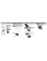
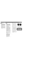
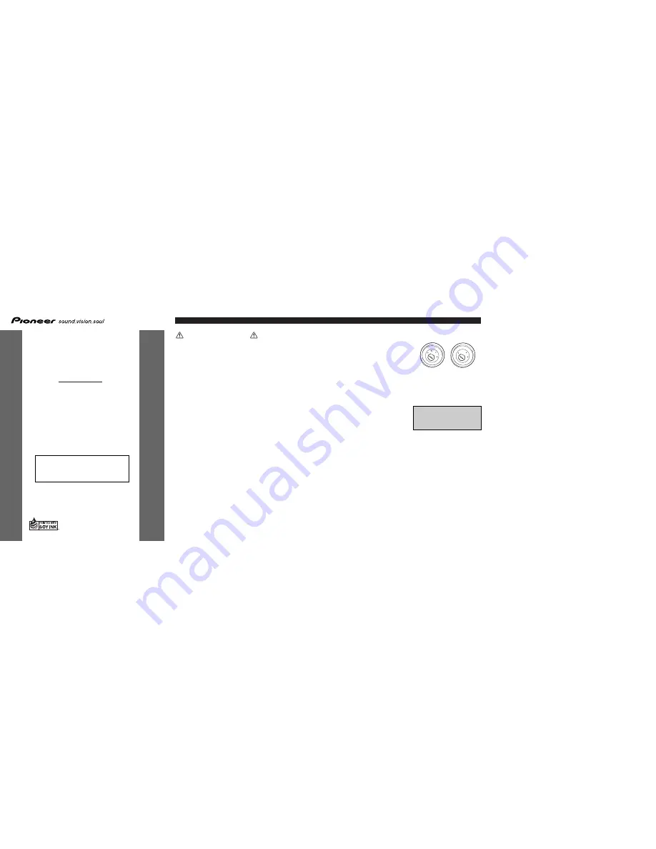
• This unit cannot be installed in a vehicle that
does not have an ACC (accessory) position on
the ignition switch.
• The black lead is ground. Please ground this lead
separately from the ground of high-current prod-
ucts such as power amps.
If you ground the products together and the ground
becomes detached, there is a risk of damage to the
products or fire.
No ACC position
ACC position
ON
S
T
A
R
T
O
FF
ACC
ON
S
T
A
R
T
O
FF
• Cords for this product and those for other prod-
ucts may be different colors even if they have
the same function. When connecting this product
to another product, refer to the supplied manuals
of both products and connect cords that have the
same function.


