54
XR-VS77, XR-VS55
Electrical Adjustment
Check the following before starting.
(1) Confirm that the tape speed adjustment has been completed.
(2) Clean the heads and demagnetize them using a head eraser.
(3) Set the measurement level to 0 dBV = 1 Vrms.
(4) Use the specified tape for adjustment. Use the labeled (A)
side of the test tape.
STD-331E : For playback check
STD-632 : Normal blank tape
(5) Provide yourself with the following measuring devides:
•
AC millivoltmeter
•
Low-frequency oscillator
•
Attenuator
•
Oscilloscope
(6) Adjust both right and left channels unless otherwise specified.
(7) Turn the DOLBY NR switch off unless otherwize specified.
(8) Warm up the unit for several minutes before adjustment.
In particular, be sure to warm up the unit in the REC/PLAY
mode for 3 to 5 minutes before starting recording/playback
frequency characteristics adjustment.
(9) Always follow the indicated adjustment order.
Otherwise, a complete adjustment may not be achieved.
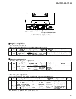
Playback Adjustment (Decks I and II)
(1) Head Azimuth Adjustment
(2) Playback Level Adjustment
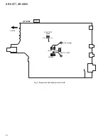
Recording Adjustment (Deck I)
(1) Bias Oscillation Frequency Adjustment
(2) Recording Bias Adjustment
(3) Recording Level Adjustment.
(4) ALC Operation Check
* As the reference recording level is 250nwb/m for STD-331E, the
recording level will be higher by 4 dB for STD-331B (160nwb/m).
When adjusting, pay carefull attention to the type of tape used.
6.2 CASSETTE DECK SECTION
6.2.1 For XR-VS77
•
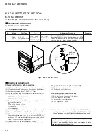
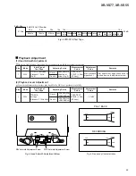
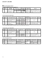
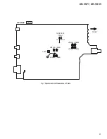
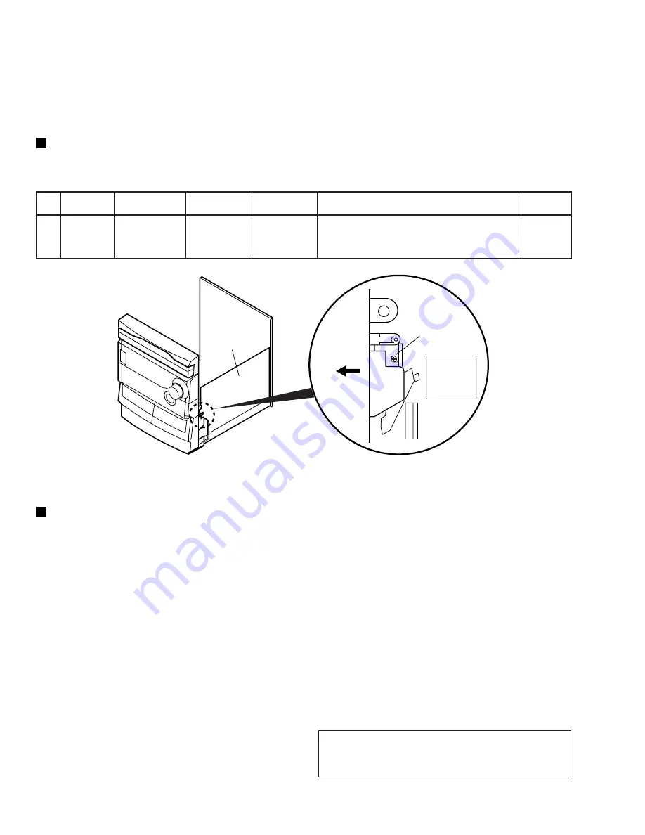
Adjustment points and test points are shown in Fig.3, Fig.5 and Fig.7.
Mechanical Adjustment
•
Test tape: NCT-111 (3kHz, 30min).
1. Tape Speed Adjustment
Dolby noise reduction manufactured under license from Dolby
Laboratories Licensing Corporation.
“DOLBY” and the double-D symbol are trademarks of Dolby
Laboratories Licensing Corporation.
.
o
N
e
d
o
M
e
p
a
T
t
s
e
T
g
n
i
t
s
u
j
d
A
s
t
n
i
o
P
t
n
e
m
e
r
u
s
a
e
M
s
t
n
i
o
P
e
r
u
d
e
c
o
r
P
t
n
e
m
t
s
u
j
d
A
s
k
r
a
m
e
R
1
k
c
e
D
I
Y
A
L
P
1
1
1
-
T
C
N
)
z
H
k
3
:
k
c
a
b
y
a
l
P
(
n
o
R
V
.
J
D
A
E
T
T
E
S
S
A
C
)
3
.
g
i
F
(
A
H
C
E
M
T
S
E
T
E
P
A
T
)
h
c
R
(
T
N
I
O
P
)
y
s
s
A
F
A
(
g
n
i
d
a
e
r
e
h
t
t
a
h
t
o
s
t
s
u
j
d
a
d
n
a
W
S
Y
A
L
P
e
h
t
s
s
e
r
P
z
H
0
0
0
3
s
e
m
o
c
e
b
±
r
e
t
t
u
l
f
&
w
o
w
t
a
h
t
m
r
i
f
n
o
C
.
z
H
0
2
m
r
i
f
n
o
c
,
n
o
i
t
c
e
r
i
d
e
s
r
e
v
e
r
e
h
t
n
i
(
%
3
.
0
w
o
l
e
b
s
i
l
e
v
e
l
z
H
0
0
0
3
n
i
h
t
i
w
s
i
g
n
i
d
a
e
r
e
h
t
t
a
h
t
±
.
)
z
H
0
6
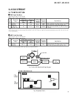
Front Side
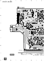
AF Assy
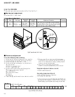
Fig.3 Tape Speed ADJ. Point
Cassette
Mechanism
Section
(Side View)
Tape Speed
ADJ. VR

