XV-DV740
100
1
2
4
1
2
3
4
C
D
F
A
B
E
*
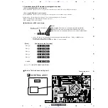
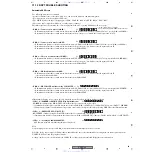
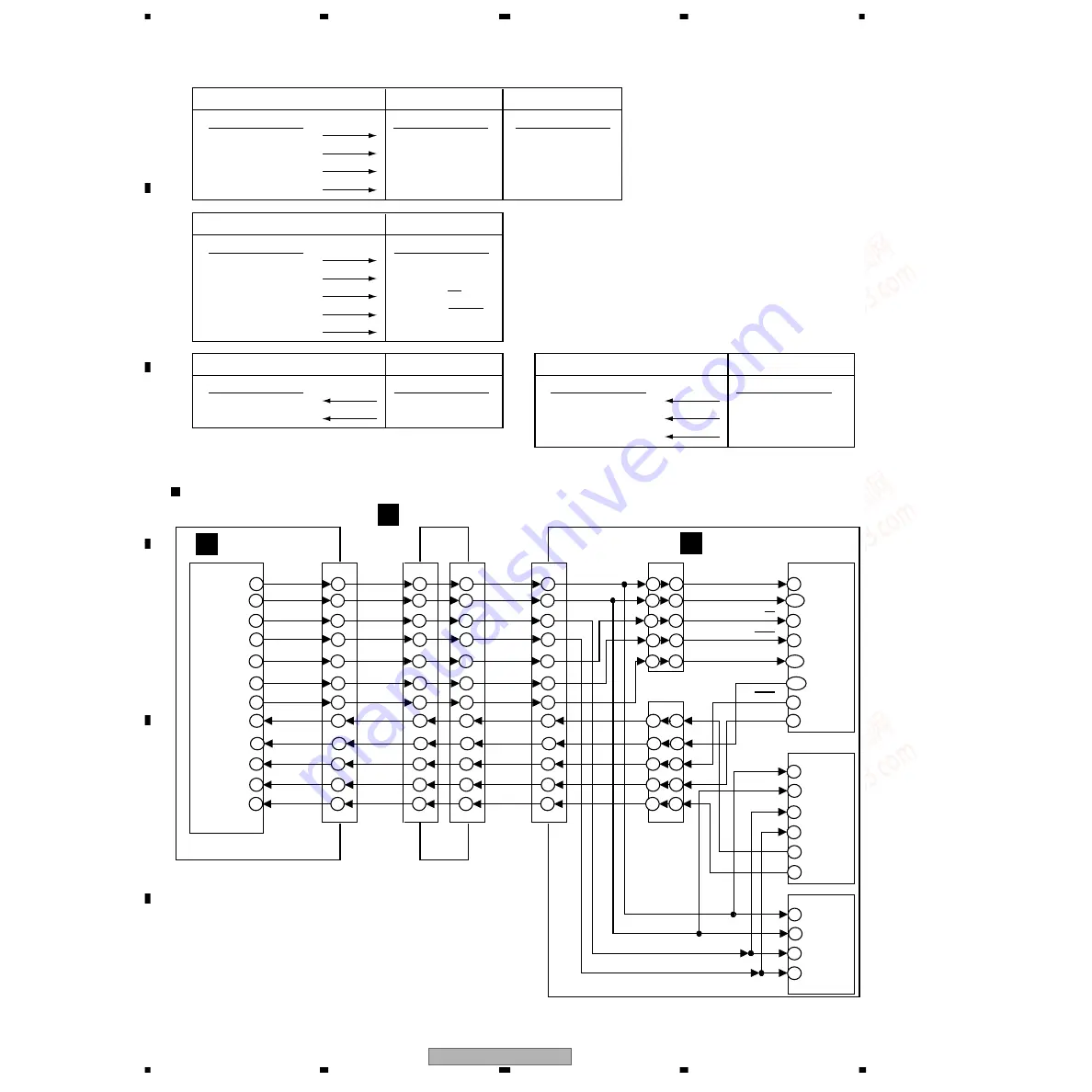
1 :
µ
-com-port which has sent the signal to IC
IC5501
µ
-com port
IC8201 DIR port
Pin No.
Pin Name
No.51
DSPCLK
No.49
DSPDI
No.79
DIRCS
No.78
DIRRST
Pin No.
Pin Name
No.34
CCLK
No.33
CDTI
No.35
CSN
No.31
PDN
Pin No.
Pin Name
No.42
CCLK
No.43
CDTI
No.41
CSN
No.17
PDN
IC8401 CODEC port
IC5501
µ
-com port
IC8501 DSP port
Pin No.
Pin Name
No.51
DSPCLK
No.49
DSPDI
No.84
DSPSS
No.85
XDSPRST
Pin No.
Pin Name
No.1
SCK
No.143 MOSI
No.2
SS
No.44
RESET
No.81
DSPMODE
No.137 MODA
IC5501
µ
-com port
IC8201 DIR port
Pin No.
Pin Name
No.80
DIRDO
No.77
DIRERR
Pin No.
Pin Name
No.32
CDTO
No.36
INT0
IC5501
µ
-com port
IC8501 DSP port
Pin No.
Pin Name
No.50
DSPDO
No.82
HREQ
No.86
DECMUTE
Pin No.
Pin Name
No.144 MISO
No.3
HREQ
No.21
PB12 MUTE
IC5501
CN5620
CN5619
CN5618
CN8011
IC8701
IC8501
DSP
Level
Shifter
Level
Shifter
IC8201
DIR
IC8401
CODEC
IC8702
DSPCLK
SCK
DSPDI
MOSI
DIRCS
SS
DIRRST
RESET
DSPSS
MODA
XDSPRST
MISO
HREQ
PB12
CCLK
CDTI
DSPCLK
DSPDI
DIRCS
DIRRST
DSPSS
XDSPRST
DSPMODE
DIRDO
DSPDO
DSPHREQ
DECMUTE
DIRERR
CSN
PDN
CDTO
INT0
CCLK
CDTI
CSN
PDN
51
49
79
78
84
85
7
5
14
15
9
8
7
5
14
15
9
8
12
13
6
11
4
16
13
15
6
5
11
12
8
7
14
9
16
4
13
15
6
5
11
12
8
7
14
9
16
4
13
11
15
17
6
16
18
14
5
12
7
9
5
3
14
4
2
6
15
8
1
143
2
44
137
144
3
21
31
34
33
35
42
32
36
43
41
17
U-com
CONTROL ASSY
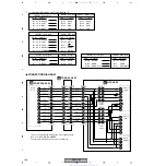
CONNECTION DIAGRAM
TRADE 3 ASSY
DSP ASSY
* This connection diagram displays the connection between
the U-com, DSP, DIR and CODEC.
The pin order is different from the true assignment.
D
G
C
www. xiaoyu163. com
QQ 376315150
9
9
2
8
9
4
2
9
8
TEL 13942296513
9
9
2
8
9
4
2
9
8
0
5
1
5
1
3
6
7
3
Q
Q
TEL 13942296513 QQ 376315150 892498299
TEL 13942296513 QQ 376315150 892498299

