XV-DV740
104
1
2
4
1
2
3
4
C
D
F
A
B
E
1
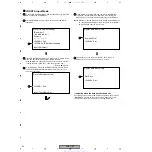
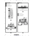
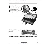
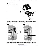
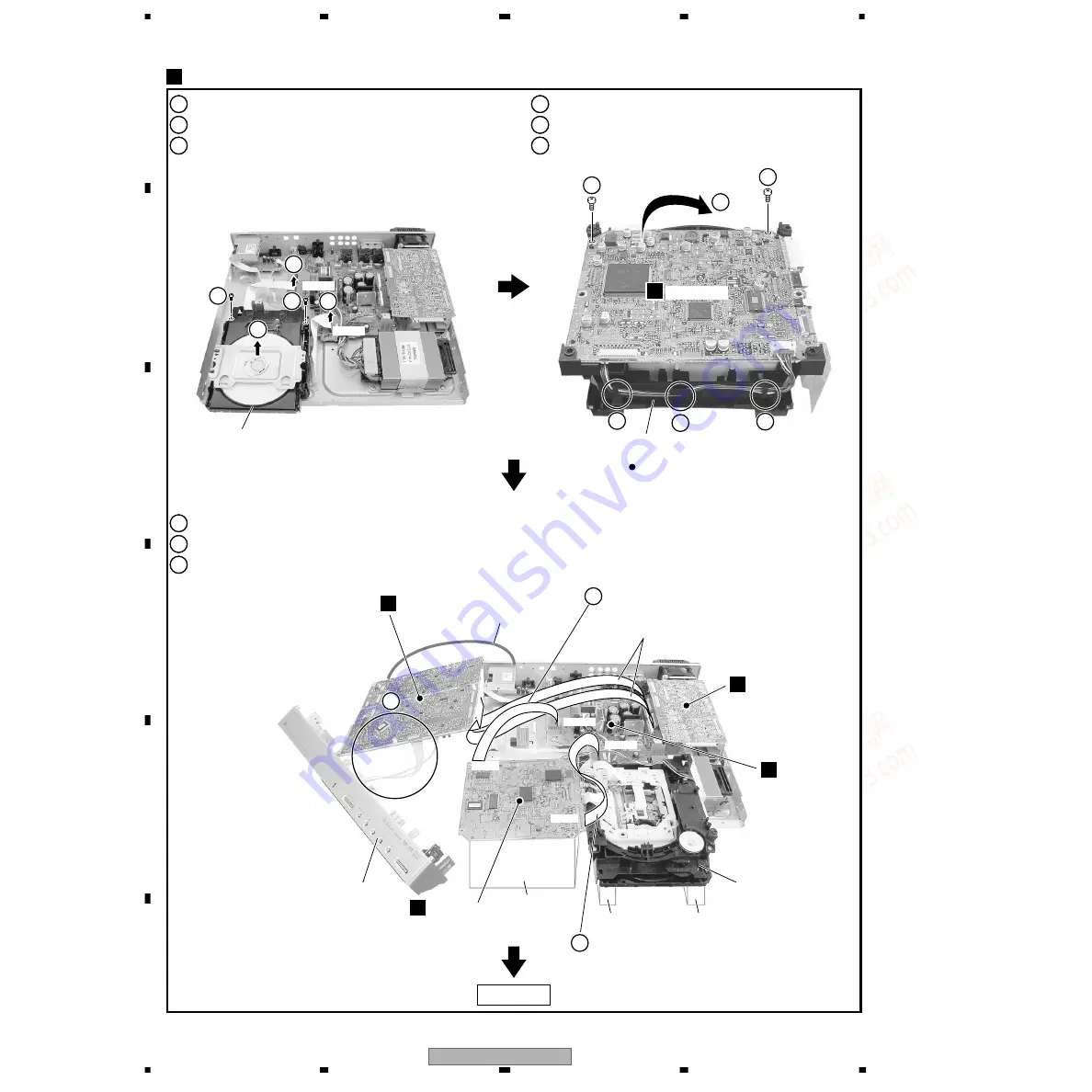
Remove the two screws.
1
1
Remove the two flexible cables.
2
1
Remove the DVD Assy.
3
1
Reattatch the CONTROL Assy and front panel section. (See Step
π
.)
7
1
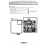
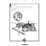
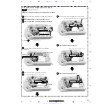
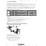
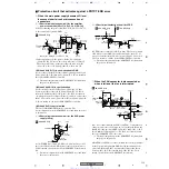
Arrange the 01 LOADER Assy and the DVDM Assy as shown in the photo below.
8
1
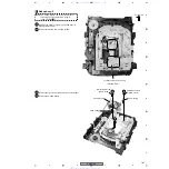
Connect the two jig cables.
9
1
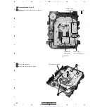
Unhook the three hooks.
4
1
Remove the two screws.
5
1
Remove and reverse the DVDM Assy.
6
DVD Assy
01 LOADER Assy
Front panel section
CONTROL Assy
F
6CH AMP
D
POWER Assy
J
DVDM Assy
B
DVDM Assy
B
Diagnosis
DVDM Assy
4
1
1
3
6
4
4
7
9
4
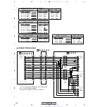
CN923
CN5102
CN8801
CN901
2
5
2
CN8801
CN5102
5
Bottom view (Rear side)
Jig cable (GGD1266)
×
2
Jig cable (GGD1160)
9
Jig cable (GGD1222)
Lead wire
(for ground)
01 LOADER Assy
(reverse state)
Spacer
Spacer
Spacer
www. xiaoyu163. com
QQ 376315150
9
9
2
8
9
4
2
9
8
TEL 13942296513
9
9
2
8
9
4
2
9
8
0
5
1
5
1
3
6
7
3
Q
Q
TEL 13942296513 QQ 376315150 892498299
TEL 13942296513 QQ 376315150 892498299

