XV-EV51
112
1
2
3
4
1
2
3
4
C
D
F
A
B
E
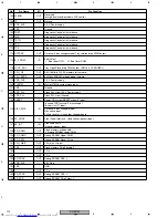
No.
Pin Name
I/O
Pin Function
105 LFEON
OUT
Reserved
for high-quality audio model's LFE control.
106 TP-
OUT
Not use.
107 VDD_3V3
−
3.3 V Power supply
108 VSS
−
Ground
109 TRST
Diagnostic Controle Unit interface
110 TMS
Diagnostic Controle Unit interface
111 TDTO
Diagnostic Controle Unit interface
112 TDTI
Diagnostic Controle Unit interface
113 TCK
Diagnostic Controle Unit interface
114 ROTDRV
OUT
Carousel 5 disc changer model Tray rotation drive PWM output.
115 B_F_ROM
IN
Boot select
'L' : Boot from DCU. 'H' : Boot form ROM.
116 LOAD_DRV
OUT
Tray Open/Close drive PWM output (SINGL & CAROUSEL)
117 CPU_OE
OUT
8M / 16M bits FLASH memory for firmware.
118 CPU_SDCK
OUT
64M bits SDRAM for debugging firmware .
119 VDD_2V5
−
2.5 V Power supply
120 CLK27M
IN
Master 27MHz system clock input.
121 VSS
−
Ground
122 VDD_PLL
−
Clock PLL circuit 2.5 V Power supply
123 VSS_PLL
−
Clock PLL circuit Ground
124 RESET
IN
Power ON system RESET signal 'L' input.
125 DISC_SNS
IN
In case of NOT carusel 5 disc changer,
this port is N.C.(input).
Carousel 5 disc changer model
Disc sense input.
Pull up resistor is in another changer board.
126 FP_XRDY
IN
Front Panel interface. Hand-shake(request) input.
127 FE_INT
IN
Front-End L6315
Interrupt request input.
128 SD_DQML
OUT
Flash memory write enable
'L'. Debug SDRAM Lower DQM.
129 SD_DQMU
OUT
Debug SDRAM Upper DQM
130 SD_RXW
Debug SDRAM Read/~Write
131 CPU_WAIT
OUT
CPU wait 'H' input
132 CE3
OUT
Flash memory Chip Eenable 'L'
133
−
OUT
TP-x
134
−
OUT
TP-x
135 SD_XRAS
OUT
Debug SDRAM RAS 'L'
136 VDD_3V3
−
3.3V Vdd
137 VSS
−
GND
138
−
OUT
TP-x
139 SD_XCAS
OUT
Debug SDRAM CAS 'L'
140 SD_XCS
OUT
Debug SDRAM Chip Select 'L'


