background image

XW-HTP550

34

1

2

3

4

1

2

3

4

C

D

F

A

B

E

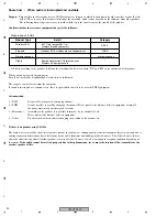
Know-how   :   When audio is interrupted and unstable

Purpose

 : This wireless speaker system usese a 2.4GHz radio wave frequency, which is a band used by other wireless system (See list 

                  below). There is a case that becomes to interrupt the the sound, and becomes unstable by the influence from other product.
                  The following knowledge is necessary to divide whether it is the interference or the trouble of the product.

Confirm whether there is some equipment that gives the influence.

* : It differs according to the product. It follows the classification if it was written "DS" and "FH" in the indication of the product.

When you cannot specify the equipment
Even if it is used in the neighborhood, it is likely to be influenced.

The category can be forecast from the symptom.
If sound is interrupted at a constant cycle, there is a possibility that it is to be near the FHSS equipment.

Action method

1 )  DSSS

It is possible to improve by changing channel.

2 )  FHSS

It is not possible to avoid by changing the channel. Please separate the distance between equipment or turn off
the power while using wireless speaker system.

3 )  Microwave

According to the product, it is possible to improve by set channel to 1ch.
Please separate the distance between equipment.

4 )  Other

Try the switch of the channel or changing the position of the product, etc.

If there is no product using 2.4GHz

The radio waves received by the wireless speaker include the radio wave coming directly from the transmitter (direct wave) and waves
coming from various directions due to reflections by the walls, furnitures and building (reflected waves). The reflected waves (due to
obstacles and reflecting objects) further produce a variety of reflected waves as well as variation in reception condition depending on
loacations. 

If the audio cannot be received properly due to this phenomenon, try to move the location of the transmitter or the 

wireless speaker a little.

Product uses 2.4GHz

Product Type

Wireless LAN

Bluetooth

FHSS

Microwave ovens

microwave oven

Headset, PDA, wireless mouse, keyboard, etc.

DSSS

802.11b,g (except 802.11a), 
Wireless broad band routers

Others

*

Some baby monitors, Cordless phones,
Wireless AV equipment, etc.

Detail

Category

Summary of Contents for XW-HTP550

Page 1: ...Remarks XW HTP550 KUCXJ AC120V Ask user to bring the Transmitter and Wireless Speaker pair set together when servicing SX 315 KUCXCN HTP 4600 KUCXCN RRV3071 S FCRW4500 XTW UC XW HTP550 KUCXJ RRV3112 AUDIO MULTI CHANNEL RECEIVER HOME THEATER SYSTEM SPEAKER SYSTEM DIGITAL WIRELESS SPEAKER SYSTEM This manual Component System Service Manual Remarks RRV3090 SX 315 KUCXCN HTP 4550DVR KUCXCN RRV3071 S FC...

Page 2: ...isual inspection nor the protection afforded by them necessarily can be obtained by using replacement components rated for voltage wattage etc Replacement parts which have these special safety characteristics are identified in this Service Manual Electrical components having such features are identified by marking with a on the schematics and on the parts list in this Service Manual The use of a s...

Page 3: ...the product Please check that neither solder debris nor screws remain inside the product 8 There should be no semi broken wires scratches melting etc on the coating of the power cord Damaged power cords may lead to fire accidents so please be sure that there are no damages If you find a damaged power cord please exchange it with a suitable one 9 There should be no spark traces or similar marks on ...

Page 4: ...AGRAM 14 3 3 MAIN LED PRIMARY and BINDER ASSYS 16 3 4 TX ASSY 18 3 5 RX ASSY 20 4 PCB CONNECTION DIAGRAM 22 4 1 MAIN and BINDER ASSYS 23 4 2 PRIMARY ASSY 25 4 3 TX ASSY 27 4 4 LED and RX ASSYS 29 5 PCB PARTS LIST 31 6 ADJUSTMENT 32 7 GENERAL INFORMATION 33 7 1 DIAGNOSIS 33 7 1 1 DIAGNOSIS NOTE 33 7 1 2 TROUBLE SHOOTING 35 7 1 3 DIAGNOSIS OF TX and RX MODULES 38 7 1 4 DIAGNOSIS OF THE AMPLIFIER SEC...

Page 5: ... characteristics Maximum power output 10W ch RMS 1kHz THD10 4Ω Continuous power output 7 5W ch 120Hz 20kHz 1 0 4Ω Music power output 18W ch DIN MUSIC 10 4Ω Speaker unit 7cm cone type x2 Weight 2 9 kg 6 lbs 6 oz Dimensions 461 5 W x 176 5 H x 95 D mm 18 3 16 W x615 16 H x33 4 D in Accessories s AC adaptor 1 RCA stereo cord 1 1 Power cord 1 Warranty card 1 Operating instructions Note The specificati...

Page 6: ...omponent parts indicates the importance of the safety factor of the part Therefore when replacing be sure to use parts of identical designation Screws adjacent to mark on product are used for disassembly For the applying amount of lubricants or glue follow the instructions in this manual In the case of no amount instructions apply as you think it appropriate NOTES 2 9 10 8 7 4 5 10 11 6 Transmitte...

Page 7: ...Power Cord ADG7021 2 AC Adaptor AWR7006 3 RCA Stereo Cord XDE3045 4 Operating Instructions ARE7353 English French NSP 5 Warranty Card ARY7045 NSP 6 Literature Bag AHG1180 7 Polyethylene Bag VHL1051 8 Packing Sheet AHG7015 9 Accessory Box NW AHB7104 10 Pad L R AHA7440 11 Packing Case AHD8338 ...

Page 8: ...XW HTP550 8 1 2 3 4 1 2 3 4 C D F A B E 2 2 TRANSMITTER SECTION 3 13 2 9 8 7 7 12 1 11 11 6 11 10 11 11 11 5 4 G E ...

Page 9: ...WU8260 2 TX Module AXF7015 3 Top Panel AAK8283 4 CS Lens AAK8133 5 CS Button T AAD7729 6 Chassis T ANA7157 7 Leg AEB7090 NSP 8 PCB Spacer 3x6 AEC7156 9 PCB Spacer AEC7546 NSP 10 Name Label T KU AAL7389 11 TORX Screw ABA7111 12 Screw with Washer ABA7124 NSP 13 Getter KU AAX8066 Use TORX driver GGK1028 or GGK1071 ...

Page 10: ... SPEAKER SECTION A A C D D C B B CONTACT SIDE NON CONTACT SIDE 6 1 3 8 2 9 7 4 5 24 33 33 33 35 36 36 36 36 36 36 36 35 33 33 33 30 35 28 16 27 22 16 26 34 33 13 33 31 29 18 37 10 13 33 33 14 12 11 11 15 23 20 21 34 19 F H D A C B Lubricating Oil GYA 009 ...

Page 11: ...70AC50 53C 12 Chassis ANA7176 13 FET Bracket A ANG7432 14 Heat Sink ANH7178 15 Spring K ABH7239 16 Rubber Leg AEB7353 17 18 Mini Clamp AEC7373 19 PCB Spacer AEC7546 20 Baffle L AMD7015 21 Baffle R AMD7016 22 Operation Panel AAK8260 23 PWR Button Assy AXG7245 24 Grille Assy AXG7254 25 Name Plate 36 AAM7013 26 Rear Case Assy AXG7255 27 Cover AAK8282 NSP 28 Angle B NSP 29 Angle A NSP 30 Name Label KU...

Page 12: ...A 5 IC8051 NJM2374AM 5V REG IC8101 NJM12904M V 5RF 3 3V REG 3 3V REG 2 8V REG POWER ID Learn ID Learn TUNED Ch 1 Ch 2 Ch 3 Ch 4 Q8501 Q8504 Ch select CN8203 12P CN5901 5P CN5902 5P V 5RF GNDD LEDP LEDTUN2 LEDTUN1 GNDD V 5RF ROUT LOUT 2 12 10 1 7 8 6 2 12 10 1 7 8 6 1 2 3 4 1 2 3 4 L Ch EEPROM R Ch VD 9 ANT2 BBIC RF IC PA ID Learn ID State Sync V 5RF CN8204 12P 8 12 11 V 9 V 9 LOUT ROUT 6 5 5 D8501...

Page 13: ...MP 5 3 8 4 1 Lch Rch 7 IC3302 LA4663 Power IC SP PROTECT Q3511 Q3451 Q3452 Q3454 Q3453 Q3455 4 5 6 9 AN1 CN2 CN3401 5P L IN VCC2 VCC1 L OUT R OUT Relay Control MAIN MAIN L L R R MUTE 11 L OUT 12 R OUT 14 B INSIDE SPEAKER AC IN RELAY DRIVE POWER RELAY RY3301 B VP B 2 8 7 R IN GND NEUTRAL LIVE FU1 S1 T1 POWER TRANSFORMER VPRE9 1 2 2 1 2 1 CN11 2 3 4 1 2 3 4 1 D11 D12 D13 D17 VA 9 VD 9 V 9RF 5 4 1 2 ...

Page 14: ...VH AKP7200 KUCXJ XKP3042 LIVE NEUTRAL 2 1 MAIN MAIN AC CORD ASG7024 AC POWER SW NC TO SPEAKER SL R SR L SR L SL R Reciever Section 12V 1ch 2ch 3ch 4ch channel 11 12 AIL AIR DC IN WIRELESS IN L R Transmitter Section GNDA Ch4 Ch3 Ch 10 9 8 7 6 Ch1 RFGND RFGND V 5RF Ch2 5 4 3 2 V 5RF 1 MAIN ASSY AWU8261 A PRIMARY ASSY AWU8266 C TX ASSY AWU8260 E TX MODULE AXF7015 G No circuit diagram ...

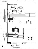
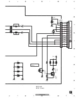
Page 15: ...T LOUT V 9 V 9 GNDRF GNDD LEDTUN1 GNDD LEDP LEDTUN2 4 5 6 7 IDlearn IDstat Sync GNDRF GNDRF 1 2 3 GNDRF V 5RF V 5RF NOTES When ordering service parts be sure to refer to EXPLODED VIEWS and PARTS LIST or PCB PARTS LIST The mark found on some component parts indicates the importance of the safety factor of the part Therefore when replacing be sure to use parts of identical designation The power supp...

Page 16: ...Y 2SA1576A STBY STBY 2 5A AEK7049 F AEK7049 F 2200 25 GNDRF GNDD STBY 1 50 STBY 100 25 TS TS 2 5A AEK7047 F AEK7047 F 7A 7A S1WB A 60SD VPRE9 NJM78M09FA V 9RF VD 9 GNDP B4PS VH 6800 25 STBY VA 9 VNF1084 330 10 50 330 330 D3SBA20 B 1 1k 1k B GNDD UDZS9R1 B 10k 220 6 3 10k 56k 47 25 1 50 56k 2SC4081 QR GNDD 220 2SC4081 220 220 3 9k 15k 390k STBY VREF5 VD 9 NP 100 10 4 7k B 10k 2SA1576A B5P VH 4 7k 4...

Page 17: ...343MC SLR 343MC GNDA STBY 470 6 3 0 01 UDZS4R7 B STBY BA4558F TS 820 VREF STBY STBY 0 01 STBY 4 7k STBY 0 01 4 7k TS 2 2 50 2 2 50 VA 9 1k 10 BA4558F 2200p TS STBY STBY STBY STBY STBY STBY TS 1k 2200p STBY 820 STBY DTC114YK GNDP UDZS4R7 B 10k 10 50 STBY STBY 10k STBY GNDP 0 0 01 STBY 100 25 STBY GNDRF GNDD STBY 6800p 4 7k 5 6k 10 50 GNDA VD 9 10k 22k 0 022 10k 22k 0 022 100k GNDRF 100k STBY STBY 4...

Page 18: ... 2k GNDRF 470 25 T STBY STBY 2 2 2 2 2 2 2 2 2 2 2 2 100 10 DC DC Converter GNDRF NJM2374AM TFB AKN7038 YB STBY YB STBY STBY 1SR154 400 TRB YB 0 01 V 12 GND STBY STBY STBY STBY 330 220p CH STBY 220p 330 CH CH 470uH DTL1122 3 6k STBY YB GNDRF 330 25 YB STBY STBY STBY STBY STBY BA05FP TLB GNDA GNDA VD 5 VA 5 V 5RF STBY 0 01 YB 47k 10 50 220p GNDA 47k CH VREF 220p CH 47k 10 50 GNDA 47k 47p CH 22k 22k...

Page 19: ...022 CN8201 R8107 C8101 STBY STBY STBY GNDD STBY VSG1024 T GNDD 1k 1k 330 270 STBY VD 5 1k SLR 343MC NPQ TS SLR 343MC NPQ TS SLR 343MC NPQ TS SLR 343MC NPQ TS 1k GNDA 820 470 6 3 VA 5 UDZS2R0 B TRB VREF 0 VA 5 8 2k GNDA 10 50 STBY STBY 10k 10k GNDRF 8 2k 10 50 0 01 YB GNDA YB YB YB YB YB STBY 1000p STBY 1000p 1000p 1000p V 5RF AKP7200 12 11 8 9 10 5 6 7 2 3 4 1 Ch 1 Ch 2 Ch 3 Ch 4 D8501 D8504 VREF ...

Page 20: ...2418 1210 GNDA GNDD VD 9 STBY GNDD GNDD 10k 2SC4081 1k GNDS STBY GNDS STBY 1 2k 1 2k 1 2k VD 9 GNDRF YB 1000p GNDRF 10 50 GNDRF 22 50 STBY 100k 100k STBY V 9 VD 9 NJM78M05FA V 5RF OUT IN CKSRYB CH CCSRCH CEAT M TS NOTES ALL CAPACITORS ARE IN µ F UNLESS OTHERWISE SPECIFIED ALL RESISTORS ARE IN Ω 1 16W CHIP TO LED ASSY GNDD LEDTUN1 LEDTUN2 LEDP GNDD FFC ADD7505 NC VD 9 GNDD NC STBY STBY TO MAIN ASSY...

Page 21: ...R8901 R8903 R8904 R8905 C8017 C8015 CN8203 GNDD GNDS STBY STBY STBY STBY GNDRF VSG1024 T GNDD 0 01 STBY 10 50 STBY STBY STBY 10 50 10k 2SC4081 SLR 343MC TS 1 2k 1 2k 1k 1 2k VD 9 STBY STBY GNDRF V 5RF AKP7200 12 11 10 8 9 7 4 5 6 2 1 3 ID Learn QR NPQ GNDA AOR AOL GNDA IDstat IDlearn GNDRF GNDRF Sync V 5RF V 5RF GNDRF F SWITCHES S8902 ID Learn RX MODULE AXF7016 H ...

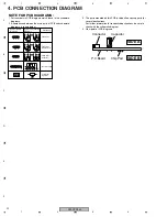
Page 22: ...ed on this PCB include all necessary parts for several destinations For further information for respective destinations be sure to check with the schematic diagram 4 View point of PCB diagrams Symbol In PCB Diagrams Symbol In Schematic Diagrams Part Name B C E D D G G S S B C E B C E D G S B C E B C E B C E Transistor Transistor with resistor Field effect transistor Resistor array 3 terminal regul...

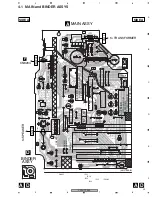
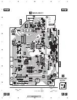
Page 23: ...W213 W161 C3313 W109 W107 W110 W108 W168 W169 W147 W149 W205 W206 W177 W220 Q3455 IC13 IC12 IC3302 IC14 IC15 IC11 NC PNE 1B1 GNDRF Production code GND GND V 9 V 9 LOUT GNDD VD 9 GND ROUT GND HEAT RESIST PRE FLUX REPLACE IC LINKS AS MARKED NC PRINTED SIDE PRINTED SIDE tolak tekan tekan BOND CAUTION IC3301 VD 9 GNDS GNDS VPRE9 GNDD GNDP VP B VP VP VP STANDBY GNDP MUTE GNDP GNDP L L R R GNDRF GNDS GN...

Page 24: ...R3391 Q3511 C3320 C3319 Q3454 R3458 R3459 Q3453 R15 R12 R11 R16 R3460 R3461 D3511 R3511 R3513 R3514 D14 D12 D13 D15 D16 D3451 D3452 C17 C18 D3453 D3371 D17 C3314 R3327 Q3307 R3321 R3323 R3322 D3303 C3315 R3325 R3326 C3316 C3318 Q3304 Q3302 Q3301 Q3305 Q3303 D3503 D3372 R3462 R3315 R3399 R17 R18 R3463 R3465 R3464 Q3451 Q3452 Q3511 Q3454 Q3453 Q3307 Q3304 Q3302 Q3301 Q3305 Q3303 IC3301 GNDD B 12 V 9...

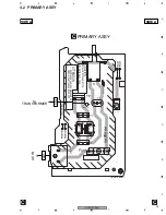
Page 25: ...H2 S1 W102 W103 W101 W104 KN1 W106 W105 W208 W209 PNE 1B1 PRIMARY AWU8266 PRIMARY ASSY FU1 REMPLACER PAR LE FUSIBLE PAR UN ATTENTION REPLACE WITH SAME TYPE AND RATINGS OF FUSE CAUTION MODELE IDENTIQUE EN INTENSITE OPEN SIDE AWU8265 CN2 to TRANSFORMER AN1 AC IN ANP7535 B PRIMARY ASSY C SIDE A SIDE A C C ...

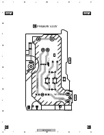
Page 26: ...XW HTP550 26 1 2 3 4 1 2 3 4 C D F A B E 2 1 R LF LIVE NEUTRAL PRIMARY A PNE 1B1 ANP7535 B PRIMARY ASSY C SIDE B SIDE B C C CN2 AN1 ...

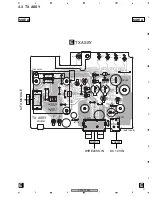
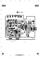
Page 27: ...W189 W178 W181 W180 W179 C8101 C8102 C8205 C8206 C8008 C8001W226 CN8201 W186 C8062 W211 W210 W223 W222 W221 W194 W203 PCB SPACER PCB SPACER PCB SPACER GND AWU8260 PNE 1B1 AXF7015 GNDA GND GNDA GND others AXF7017 MAXJ VD 5 CH4 CH3 CH2 CH1 Ch TX ASSY IC3301 GNDA GNDRF V 5RF CH1 CH3 VA 5 GNDA VREF ANP7535 B CN8201 WIRELESS IN to TX MODULE JA8202 DC 12V IN JA8001 TX ASSY E SIDE A SIDE A E E ...

Page 28: ...8512 D8001 D8004 Q8501 IC8052 L8201 L8202 D8102 IC8101 C8103 C8104 R8505 R8506 R8507 R8508 C8113 C8010 C8901 C8009 C8204 C8203 C8202 C8201 C8002 Q8502 Q8503 Q8504 R8201 R8202 C8021 R8206 R8203 R8204 R8205 C8024 C8025 C8064 Q8501 Q8502 Q8503 Q8504 IC8051 IC8052 IC8101 GND B 5 4 1 8 GNDA GND GNDA GND V 5 AWU8260 A 5 4 1 8 PCB SPACER VREF V 5RF GNDA GNDA VA 5 GNDRF CH3 CH1 PNE 1B1 VD 5 1 12 1 V 5RF V...

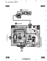
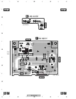
Page 29: ...02 W219 D8006 W218 W215 W216 W217 W225 W228 W214 W200 IC8003 PCB SPACER PCB SPACER PCB SPACER AWU8262 PNE 1B1 LED ASSY GNDRF A TUNED POWER AXF7016 V 9 RX ASSY AWU8263 GNDD LEDTUN1 LEDTUN2 LEDPOW GNDD UPPER CONTACT CONTACT SIDE VD 9 GND GNDRF GNDRF PNE 1B1 CONNECT SIDE NJM78M05 GNDD GNDRF VD 9 GNDRF CN8204 CN8203 CN5902 CN5901 CN3701 to RX MODULE A ANP7535 B ANP7535 B RX ASSY F LED ASSY B SIDE A SI...

Page 30: ...1 Q5901 Q8901 1 GND TUNED POWER V 9 V 5RF 1 V 9 AWU8263 LED ASSY AWU8262 LEDTUN1 LEDTUN2 1 GNDD GNDD LEDPOW GNDD LEDTUN1 LEDTUN2 LEDPOW GNDD 5 VD 9 GNDRF GNDD ROUT GNDRF GNDA LOUT GNDRF V 9 1 NC NC GNDD VD 9 GNDRF VD 9 GNDRF GNDRF GNDRF GNDRF OUT G IN 5 1 12 1 PNE 1B1 PNE 1B1 12 GNDRF 1 V 5RF GNDRF GNDRF SYNC IDSTAT IDLEARN UGND LOUT GNDA ROUT ANP7535 B ANP7535 B RX ASSY F LED ASSY B SIDE B SIDE B...

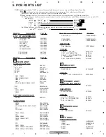
Page 31: ...47 IC11 IC14 AEK7049 IC3301 BA4558F HT IC3302 LA4663 IC15 NJM78M09FA Q3451 Q3452 2SA1576A Q3453 Q3454 Q3511 2SC4081 Q3455 2SD1858X Q3305 DTC114YK D12 D16 D3451 D3503 D3511 1SS355 D11 D3SBA20 B D17 S1WB A 60SD D3304 D3371 UDZS4R7 B D3453 UDZS9R1 B SWITCHES AND RELAYS RY3301 ASR7019 CAPACITORS C3310 CEAL101M25 C3451 CEANP101M10 C15 C3306 C3312 C3371 C3372 CEAT100M50 C19 CEAT101M25 C12 C3512 CEAT1R0M...

Page 32: ...STORS Other Resistors RS1 16S J OTHERS JA8001 DC POWER JACK AKN7038 CN8201 B TO B CONNECTOR 12P AKP7200 JA8202 2P PIN JACK PKB1034 FRX ASSY SEMICONDUCTORS IC8003 NJM78M05FA Q5901 Q8901 2SC4081 D8901 SLR 343MC SWITCHES S8902 VSG1024 CAPACITORS C8013 C8211 C8212 CEAT100M50 C8014 CEAT220M50 C8026 CKSRYB102K50 C8902 CKSRYB103K50 RESISTORS Other Resistors RS1 16S J OTHERS CN5901 5P FFC CONNECTOR 52045 ...

Page 33: ...rocess v If Receiver finishes learning D8901 will change to lighting from blinking Note The ID learning process won t be enabled if only press the button for either Transmitter or Receiver one side It must press two sides in the same time Do not use the ID learning setting to customer s receiver unit when there is no customer s transmitter unit Using ID learning setting in this case ID data of the...

Page 34: ...by changing the channel Please separate the distance between equipment or turn off the power while using wireless speaker system 3 Microwave According to the product it is possible to improve by set channel to 1ch Please separate the distance between equipment 4 Other Try the switch of the channel or changing the position of the product etc If there is no product using 2 4GHz The radio waves recei...

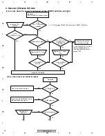
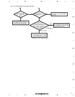
Page 35: ...module may be broken Replace the module Is the AC adaptor s Voltage active Is either of potential of CN8201 pin5 8 active Is V 5 voltage active CN8201 pin 1 2 C8054 No No No Yes Yes Yes 2 In a case where no sound is output No sound Check the Audio Lines sequentially from WIRELESS IN to CN8201 The module may be broken Replace the module Is TUNED LED in Receiver lit No The module may be broken Repla...

Page 36: ...IC14 in MAIN Assy broken Insert the FFC correctly Replace the FU1 fuse No No No No No No Yes Is the POWER LED lit Yes Yes Is the POWER LED lit Yes Yes Is the POWER LED lit Yes Yes Replace IC11 and or IC14 Yes Inspection completed As the circuit for 9 V is most likely to have been short circuited check the circuits around IC15 2 In a case where no sound is output No sound Is TUNED LED lit Is the re...

Page 37: ...ely that the RX module or Transmitter section is in failure The B and ground circuits are most likely to be short circuited or IC3302 is likely to be broken Detach the RX module then by inputting an audio signal to the jumper lead for servicing 2 check if sound is output No sound Sound is output Are the IC12 and IC13 in MAIN Assy broken Yes To diagnosis of the Transmitter section A B 2 See page 39...

Page 38: ...g ID learning setting in this case ID data of the customer s receiver unit will be changed to the another ID that is same as a substitute transmitter unit When using ID learning setting to customer s receiver unit without customer s transmitter unit ask customer to bring the transmitter unit and set the ID number for each pair of the customer s transmitter and receiver unit 2 When there is no othe...

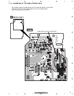
Page 39: ...60 R3461 D3511 R3511 R3513 R3514 D14 D12 D13 D15 D16 D3451 D3452 D3453 D3371 D17 D3503 2 315 R17 R18 R3463 R3465 R3464 GNDD 12 V 9 11 V 9 10 GNDRF 9 GNDRF 8 LOUT 7 GNDA 6 ROUT 5 GNDRF 4 VD 9 3 GNDD 2 NC 1 NC 4 5 1 VD 9 GNDS GNDS VREF GNDRF GNDD VPRE9 GNDS 8 Rin Lin ForSERVICE Rch Lch GNDD VA 9 12 1 GNDA MAIN ASSY Jumper Wire for service for Signal Input The Amplifier section can be diagnosed even ...

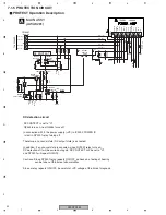
Page 40: ... VP voltage at the time of diagnosis PROTECT Operation Description A MAIN ASSY AWU8261 E C B B 4 3 E C B E B C E E C C B 1 2 3 1 2 5 4 13 11 14 12 5 7 8 9 2 6 10 3 4 1 Q3454 R3463 C3464 C3463 D3452 D3451 RY3301 R3464 R3456 Q3455 Q3451 D3453 C3462 R3459 R3465 Q3453 R3461 R3460 R3462 R3458 C3451 R3455 R3457 Q3452 R3451 R3452 R3453 R3454 C3311 C3310 CN3401 RY3301 C3312 C3313 IC3302 220 6 3 2SC2412K Q...

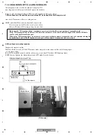
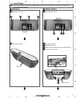
Page 41: ... 1 2 2 1 Remove the three screws 2 Remove the two screws 3 Release the two wires 4 Disconnect the one connector and the one flexible cables 5 Pull out the chassis section Chassis Section 2 Note Even if the unit shown in the photos and illustrations in this manual may differ from your product the procedures described here are common 1 1 2 2 3 3 5 4 4 Chassis section ...

Page 42: ... E PCB Location Arrangement of the wires Power supply section PRIMARY Assy Slit Slit PCB binder RX Module C MAIN Assy A RX Assy F H BINDER Assy D LED Assy B Speaker section Angle B Mini Clamp MAIN Assy MAIN Assy BINDER Assy Slit PCB binder ...

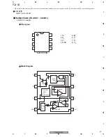
Page 43: ...ormation shown in the list is basic information and may not correspond exactly to that shown in the schematic diagrams List of IC NJM2374AM 1 CS 2 ES 3 CT 4 GND 5 IN 6 V 7 SI 8 CD 1 4 3 2 8 5 6 7 1 1 5A MAX ON DUTY 9 1 OSC Section 4 3 2 8 5 6 7 V ES GND PW LOGIC M R S Q Vref 1 25V 2 CD CT CS SI IN Vth 300mV Ipk Sense PWM COMP ERR AMP 160Ω ...

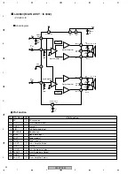
Page 44: ...Amplifier CH 1 CH 2 Ripple Filter Starting Time 7 8 5V STAND BY V CC1 VCC2 VCC 0 1uF 0 1uF 0 1uF LA4663 MAIN ASSY IC3302 POWER IC Blockdiagram Pin Function No Pin Name I O Pin Function 1 RF O RF connection 2 R IN I R ch Audio data input 3 GND A Ground A 4 L IN I L ch Audio data input 5 STANDBY I Standby input 6 MUTE I Signal Mute Input Power supply 1 Power supply 2 7 VCC1 8 VCC2 9 L OUT O L ch Amp...

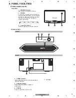
Page 45: ...y selecting another channel Each time you press the button the channel changes sequentially 3 Transmitter antenna Transmits signals to the wireless speaker CH 2 CH 3 CH 4 CH 1 Upper POWER OFF ON TUNED POWER OFF ON TUNED AC IN Back 4 TUNED indicator Lights when the signal from the transmitter is properly received 5 POWER indicator Lights when the wireless speaker is switched on 6 POWER Press to swi...

Reviews: