XW-HTP550
38
1
2
3
4
1
2
3
4
C
D
F
A
B
E
7.1.3 DIAGNOSIS OF TX and RX MODULES
After diagnosis, in the case that the module is judged to NG,
since diagnosis of a failure part is difficult, replace the modules.
It may be able to distinguish which is NG between Transmitter and Receiver simply.
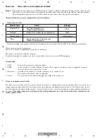
1. When there are a transmitter and a wireless SP as a substitute for the repair unit.
cross-check Transmitter & Receiver with good one.
NOTE : individual ID is written in the module respectively.
It is necessary to write ID in the case of a cross-check.
Refer to "Method of ID learning setting" for a method.
*
Do not use the "ID learning setting" to customer's receiver unit when there is no customer's transmitter unit.
Using "ID learning setting" in this case, ID data of the customer's receiver unit will be changed to the another ID that is
same as a substitute transmitter unit.
When using "ID learning setting" to customer's receiver unit without customer's transmitter unit, ask customer to bring the
transmitter unit and set the ID number for each pair of the customer's transmitter and receiver unit.
2. When there is no other module.
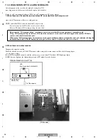
Diagnosis by simple detection
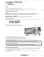
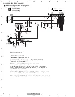
Touch the shield case side of C64 of TX module with a simple detection circuit tool like the following figure.
(see the figure below)
In case RF is amplified correctly, and the radio wave goes out from TX module, LED lights up thinly.
If LED does not light up, the transmitting circuit of TX module may be broken.
Check point
[TX Module]
Shield Case
LED
(E.g. Parts No. SLR-343MC)
Shottky
diode
Shottky
diode
(E.g. Parts No.
HSM107S)
To Check point
Simple detection circuit Tool

