f.
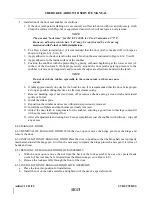
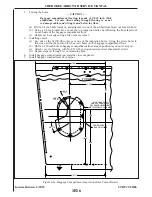
Installation of the door seal snubber is as follows:
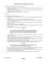
1. If the door jamb paint is flaking or is excessively scuffed, rub down with wet and dry emery cloth.
Clean the surface with Prep-Sol or equivalent cleaner which will not leave an oily residue.
NOTE
The normal “tack time” for 3M EC 1300L is 30 to 45 minutes at 75° F.
H o w e v e r, adhesive which has “set” may be reactivated by a clean rag
moistened with Toluol or Methylethylketone.
2. To effect a clean installation it is recommended that the door jamb is masked off with tape as
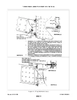
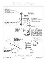
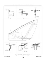
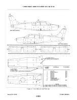
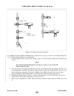
3. Apply adhesive to the door jamb with a small brush on the area indicated in Figure 4-7a. View D.
4. Apply adhesive to the inside surface of the snubber.
5. Position the snubber with the protruding leg facing outboard beginning at the lower center (±2
inches) of the door jamb. Work progressively around the door jamb applying pressure to the
snubber to remove any trapped air and to ensure the edges are effectively bonded to the jamb.
NOTE
Do not stretch the rubber, especially in the corner areas, as this can cause
cracks.
6. It takes approximately one day for the bond to cure. It is recommended that the door be kept open
as long as possible during this time to effect maximum curing.
7. Remove masking tape if used and clean off excessive adhesive using a clean cloth and mineral
spirits or Toluol.
8. Install the striker plate.
9. Reposition the windlace and secure with retainers previously removed.
10. Install the scuff plate and door holder previously removed.
11. Adjust the door latch to compensate for the snubber, ensuring a good door to fuselage contour fit
with no increase in latching effort.
12. After all adjustments and curing have been accomplished, coat the snubber with silicone - wipe off
any excess.
4-48.BAGGAGE DOOR.
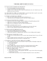
4-49. R E M O VAL OF BAGGAGE DOOR. With the door open remove the hinge pin from the hinge and
remove the door.
4-50. INSTALLATION OF BAGGAGE DOOR. Place the door in position so that the hinge halves are properly
matched and install the hinge pin. It will not be necessary to replace the hinge pin with a new pin if it is free of
bends and wear.
4-51.REMOVAL OF BAGGAGE DOOR LOCK ASSEMBLY
a.
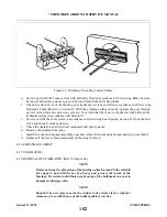
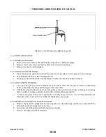
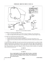
With the door open remove the nut from the back of the lock assembly by use of a special made
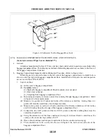
wrench. (This tool may be fabricated from the dimensions given in Figure 4-8.)
b. Remove the lock assembly through the front of the door.
4-52. INSTALLATION OF BAGGAGE DOOR LOCK ASSEMBLY.
a.
Place the lock into position for installation.
b. Install the nut on the lock assembly and tighten with the use of a special wrench.
Added: 11/21/80
1E13
CHEROKEE ARROW III SERVICE MANUAL
STRUCTURES
Summary of Contents for ARROW III
Page 4: ...THIS PAGE INTENTIONALLY LEFT BLANK 1A4...
Page 12: ...THIS PAGE INTENTIONALLY LEFT BLANK 1A12...
Page 94: ...Figure 4 2 Wing Installation Revised 2 13 89 1D22 CHEROKEE ARROW III SERVICE MANUAL STRUCTURES...
Page 171: ...lH3 INTENTIONALLY LEFT BLANK...
Page 172: ...lH4 INTENTIONALLY LEFT BLANK...
Page 286: ...THIS PAGE INTENTIONALLY LEFT BLANK Revised 2 13 89 2A8...
Page 528: ...INTENTIONALLY LEFT BLANK 2K10 THRU 2L24 2K10...

