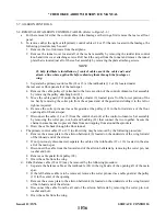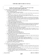
TABLE IV-II
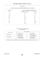
MAXIMUM DISTANCE BETWEEN SUPPORTS FOR FLUID TUBING
TUBE OD
DISTANCE BETWEEN SUPPORTS (IN.)
(IN.)
ALUMINUM ALLOY
STEEL
1/8
9-1/2
11-1/2
3/16
12
14
1/4
13-1/2
16
5/16
15
18
3/8
16-1/2
20
1/2
19
23
5/8
22
25-1/2
3/4
24
27-1/2
1
26-1/2
30
TABLE IV-III. Hose clamp tightening,
(initial installation).
Types of clamps
Types of hose
Worm screw type
All other types
Self sealing
Finger-tight-plus
Finger-tight-plus
2 complete turns
2 1/2 complete turns
All other hose
Finger-tight-plus
Finger-tight-plus
1 1/4 complete turns
2 complete turns
lf clamps do not seal at specified tightening, examine hose connection and replace parts as necessary.
Added: 5/1/80
1F2
* CHEROKEE ARROW III SERVICE MANUAL
STRUCTURES
Summary of Contents for ARROW III
Page 4: ...THIS PAGE INTENTIONALLY LEFT BLANK 1A4...
Page 12: ...THIS PAGE INTENTIONALLY LEFT BLANK 1A12...
Page 94: ...Figure 4 2 Wing Installation Revised 2 13 89 1D22 CHEROKEE ARROW III SERVICE MANUAL STRUCTURES...
Page 171: ...lH3 INTENTIONALLY LEFT BLANK...
Page 172: ...lH4 INTENTIONALLY LEFT BLANK...
Page 286: ...THIS PAGE INTENTIONALLY LEFT BLANK Revised 2 13 89 2A8...
Page 528: ...INTENTIONALLY LEFT BLANK 2K10 THRU 2L24 2K10...

