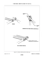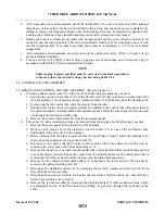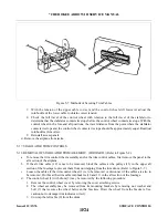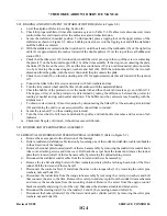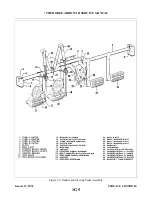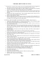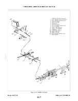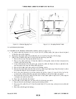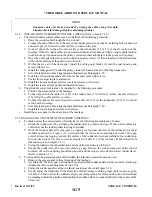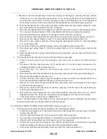
c. Set cable tension and check rigging and adjustment per Paragraph 5-22. Check safety of all turnbuckles.
d. Install the tunnel cover on the tunnel and secure with screws.
e.
Install the carpet over the floor tunnel.
f.
Install the cover over the trim control wheel and secure with screws and special washers.
g. Install the floor panel and seat belt attachments aft of the main spar and secure panel with screws.
h. Install the panel to the aft section of the airplane and the seats.
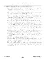
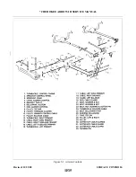
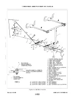
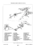
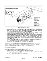
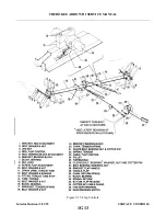
5-20 REMOVAL OF STABILATOR TRIM ASSEMBLY. (AFT ) (Refer to Figure 5-8.)
a Remove the access panel to the aft section of the fuselage.
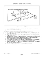
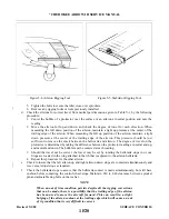
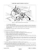
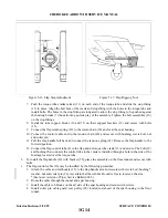
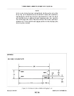
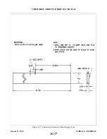
b. Block the trim cables at the first set of pulleys (33) forward of the cable turnbuckles (10 and 11) in the
aft section of the fuselage by a method shown in Figure 5-7.
c.
Disconnect the cable (12) at the turnbuckles (10 and 11) in the aft section of the fuselage.
d. Remove the tail cone by removing its attaching screws.
e.
f.
g. Remove the snap ring (32), washer (31) and thrust washer (30) from the bottom of the barrel.
h. Disconnect the diagonal rib (22) from the horizontal rib (16) that supports the trim assembly by
removing the four attaching nuts, washers and bolts.
i.
Draw the trim cable (12) from the fuselage.
5-21. INSTALLATION OF STABILATOR TRIM ASSEMBLY. (AFT.) (Refer to Figure 5-8.)
a.
Wrap the trim barrel (20) by first laying the center (as measured equally from each end to the center of
the cable) of the trim cable (12) in the slot of the barrel, Bring the upper cable through the diagonal
slot in the flange at the upper end of the barrel and wrap down in a counterclockwise direction. Bring
the lower cable through the diagonal slot in the lower end of the barrel and wrap up in a clockwise
direction. Wrap the cable as evenly as possible to obtain 23 wraps on the barrel as viewed from the
side opposite the slot and with the cables extending out from the slotted side.
b. Block both cables by clamping them between two pieces of wood laid next to the wraps to prevent
them from unwrapping.
c.
Ascertain that the barrel bushings (19 and 29) are installed in the rib plate (17) and clip (21).
Attach the bottom diagonal rib (22) to horizontal rib (16) and secure with bolt, washers and nuts.
e.
Install the thrust washer (30), washer (31) and snap ring (32) on the lower end of the barrel.
f.
g. Route the cables into the fuselage and attach the ends to the forward trim cables (8 and 9).
h. Remove the blocks that are holding the forward cables tight and aft cables at the barrel.
i.
Set cable tension and check rigging and adjustment per Paragraph 5-22. Check safety of all
turnbuckles.
j.
Install the tail cone and secure with screws.
k. Install the access panel to the aft section of the fuselage.
Revised 12/11/78
1G2
* CHEROKEE ARROW III SERVICE MANUAL
SURFACE CONTROLS
Summary of Contents for ARROW III
Page 4: ...THIS PAGE INTENTIONALLY LEFT BLANK 1A4...
Page 12: ...THIS PAGE INTENTIONALLY LEFT BLANK 1A12...
Page 94: ...Figure 4 2 Wing Installation Revised 2 13 89 1D22 CHEROKEE ARROW III SERVICE MANUAL STRUCTURES...
Page 171: ...lH3 INTENTIONALLY LEFT BLANK...
Page 172: ...lH4 INTENTIONALLY LEFT BLANK...
Page 286: ...THIS PAGE INTENTIONALLY LEFT BLANK Revised 2 13 89 2A8...
Page 528: ...INTENTIONALLY LEFT BLANK 2K10 THRU 2L24 2K10...

