1-8. HYDRAULIC SYSTEM. The hydraulic system incorporates an electrically driven pump which is
controlled by a selector lever on the instrument panel which in turn operates the retraction and extension of the
landing gear.
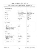
1-9. BRAKE SYSTEM. The brake system is operated hydraulically and controlled by a hand lever connected
to a single brake cylinder that operates both wheel brakes, plus individually operated toe brakes.
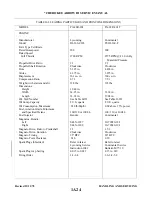
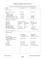
1-10. ENGINE Engine models, rated horsepower and other related information may be found in Table II-I of
Section II.
1-11.PROPELLER. A constant speed propeller is installed and controlled by an engine mounted governor
which is controlled by a lever on the power quadrant in the cockpit. Proeller specifications may be found in
Table II-I of Section II and Tble VIII-I or VIII A-I of Section VIII and VIIIA.
1-12.FUEL SYSTEM. The fuel system consists of an aluminum tank in the leading edge of the wings, a
stainer bowl with fuel screen, and electrical auxiliary fuel pump and an engine driven fuel pump.
1-13.FLIGHT CONTROLS. The flight controls are conventional equipment, consisting of a control wheel
which operates the ailerons and stabilator, and pedals which operate the rudder. Duplicate controls are
provided for the copilot.
1-14. CABIN HEATER, DEFROSTER, AND FRESH AIR SYSTEM. Heated air for the cabin and defroster is
obtained directly from the exhaust system muffler shroud. Fresh air is picked up from an inlet in the leading
edge of each wing and from an inlet in the upper leading edge of fin. The air is routed through the wings to
individually controlled outlets located just forward of each seat. The fresh air from the fin is routed to
overhead vents.
1-15. RADIO. Provisions are provided for the installations of various radio equipment along with microphone
and other radio navigation equipment.
1-16. INSTRUMENT AND AUTOPILOT SYSTEM. Provisions for instrument installation include panels for
engine instruments and advanced instruments, as well as for an Autopilot system.
Issued: 12/15/76
1A15
CHEROKEE ARROW III SERVICE MANUAL
INTRODUCTION
Summary of Contents for ARROW III
Page 4: ...THIS PAGE INTENTIONALLY LEFT BLANK 1A4...
Page 12: ...THIS PAGE INTENTIONALLY LEFT BLANK 1A12...
Page 94: ...Figure 4 2 Wing Installation Revised 2 13 89 1D22 CHEROKEE ARROW III SERVICE MANUAL STRUCTURES...
Page 171: ...lH3 INTENTIONALLY LEFT BLANK...
Page 172: ...lH4 INTENTIONALLY LEFT BLANK...
Page 286: ...THIS PAGE INTENTIONALLY LEFT BLANK Revised 2 13 89 2A8...
Page 528: ...INTENTIONALLY LEFT BLANK 2K10 THRU 2L24 2K10...


