NOTE
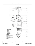
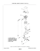
This adjustment will require two persons, a qualified pilot and a mechanic
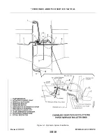
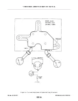
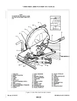
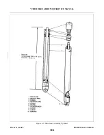
to set the actuator adjustment screw (2).
1. Remove the bottom of the rear seat.
2. The pivot screw (20) should be torqued 8 to 10 inch-pounds.
3. Loosen the jam nut (28) of the adjustment screw (2).
4. Ascertain that the electrical switch (21) will actuate with the use of the emergency gear extension
lever.
5. Fly the airplane (refer to Owner’s Handbook). Should the spring tension be out of adjustment very
much, it may be necessary to assist gear retraction with the use of the emergency gear extension
lever moved to the up override position.
6. Loosen the adjustment screw (2) by turning counterclockwise until spring (24) tension is free.
WARNING
While making adjustments, do not lay tools in area exposed by the removal
of floorboard. This may interfere with airplane controls.
7. With the airplane at a safe altitude, slow the airplane to a glide of 120 KIAS for PA-28R-201T or
110 KIAS for PA-28R-201 with the gear selector handle up and the throttle reduced to power OFF.
(Gear unsafe light and horn will indicate when power is reduced.) At 120 KIAS for 28R-201T or
110 KIAS for 28R-201, slow the airplane at a rate of one (1) knot per second until 103 KIAS for
PA-28R-201T or 95 KIAS for PA28R-201 is obtained, hold the airplane at this speed.
NOTE
Adjustment of the nut (32) may be necessary to increase or decrease the
spread between the gear up and gear down actuation speeds. To expand the
spread between these speeds, loosen the nut. Tighten the nut to bring the
airspeeds closer together. Whenever the nut is adjusted, it may be necessary
to readjust the tension on the springs (24) and to repeat the nut adjustment
procedure. If the eccentric bolt (35) is installed on the unit being adjusted,
CAUTION should be observed so as not to disturb its position in relation to
the rest of the unit.
8. With the glide established, turn the adjustment screw (2) clockwise until the gear drops. (First
indication of gear dropping will be that the gear unsafe light comes ON.)
9. Climb again to a safe altitude and check that the gear drops at the correct airspeed.
10. Land the airplane and tighten the adjustment screw jam nut (28).
Revised: 2/13/89
1H24
* CHEROKEE ARROW III SERVICE MANUAL
HYDRAULIC SYSTEM
Summary of Contents for ARROW III
Page 4: ...THIS PAGE INTENTIONALLY LEFT BLANK 1A4...
Page 12: ...THIS PAGE INTENTIONALLY LEFT BLANK 1A12...
Page 94: ...Figure 4 2 Wing Installation Revised 2 13 89 1D22 CHEROKEE ARROW III SERVICE MANUAL STRUCTURES...
Page 171: ...lH3 INTENTIONALLY LEFT BLANK...
Page 172: ...lH4 INTENTIONALLY LEFT BLANK...
Page 286: ...THIS PAGE INTENTIONALLY LEFT BLANK Revised 2 13 89 2A8...
Page 528: ...INTENTIONALLY LEFT BLANK 2K10 THRU 2L24 2K10...

