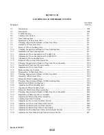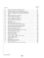
SECTION VII
LANDING GEAR AND BRAKE SYSTEM
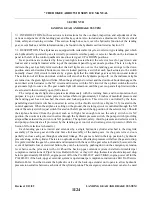
7-1. INTRODUCTION. In this section are instructions for the overhaul, inspection and adjustment of the
various components of the landing gear and brake system. Also included are adjustments for the electrical
limit, safety and warning switches. This section though does not cover the hydraulic function of the landing
gear, except brakes, and this information may be found in the hydraulic section listed as Section VI.
7-2. DESCRIPTION. The airplanes are equipped with retractable tricycle air-oil strut type landing gear which
are hydraulically operated by an electrically powered reversible pump. A selector handle on the instrument
panel to the left of the control quadrant is used to select gear UP or DOWN positions.
Gear positions are indicated by three green lights located below the selector lever for gear down and
locked, and a red light located at the top of the instrument panel for gear unsafe position. There is no light to
indicate the gear has fully retracted other than all lights are out. As the landing gear swings to the down
position and each downlock hook moves into its locked position, a switch at each hook actuates to the switch
normally closed (NC) circuit to indicate by a green light that the individual gear is safely down and locked.
The activation of all three downlock switches will also shut the hydraulic pump off. As the instrument lights
are turned on, the green lights will dim. When the gear begins to retract and the downlock hook disengages, the
down limit switch actuates to the NC circuit and in series with the NC circuit of the up limit switch allows the
gear unsafe light to come on. The gear unsafe light will remain on until the gear is up and all up limit switches
are actuated to their normally open (NO) circuit.
The red gear unsafe light also operates simultaneously with the warning horn, and in conjunction their
purpose is to give warning when power is reduced below approximately 14 inches of manifold pressure and
the landing gear has not reached the down and locked position. This circuit is controlled by the three
paralleling down limit switches connected in series with a throttle switch (see Figure 7-15) located in the
control quadrant. When the airplane is setting on the ground, the warning circuit is controlled through the NO
side of the safety switch (squat switch) located on the left gear and the up position of the selector lever. Should
the airplane be raised from the ground, such as in flight, far enough to move the safety switch to its NC
position, then current is directed in series through the hydraulic pressure switch, the pump switch (providing
airspeed has actuated the switch to its NO position). The up limit, safety, throttle, pressure and selector switch,
and pump solenoids are all protected by the landing gear control and warning circuit protector. (Refer to
Section XI for electrical schematic.)
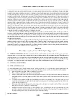
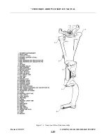
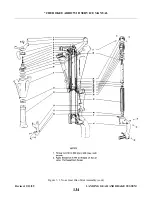
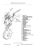
Each landing gear is retracted and extended by a single hydraulic cylinder attached to the drag link
assembly of the nose gear and the side brace link assembly of the main gears. As the gears retract, doors
partially enclose each gear through mechanical linkage. The gears are held in their up position by hydraulic
pressure along on the cylinder. There are no uplocks and loss of hydraulic pressure will allow the gears to drop.
It is preferred that the gears be extended and retracted with the use of the gear selector handle; however in the
event of hydraulic loss or electrical failure, they can be lowered by pushing down on the emergency extension
lever between the pilot seats with or without the back-up gear extender system installed or disabled per
compliance instructions of Piper Service Bulletin 866A, or they will drop themselves should airspeed drop
below approximately 103 KIAS, engine power off for the PA-28R-201T and 95 KIAS, engine power off for the
PA-28R-201 if the back-up gear extender system is operational per compliance instructions Part II of Service
Bulletin 866A. In either instant the hydraulic valve of the back-up extender unit opens to allow hydraulic
pressure to neutralize between each side of the cylinder pistons. The emergency extension lever can also be used
Revised: 2/13/89
1I24
* CHEROKEE ARROW III SERVICE MANUAL
LANDING GEAR AND BRAKE SYSTEM
Summary of Contents for ARROW III
Page 4: ...THIS PAGE INTENTIONALLY LEFT BLANK 1A4...
Page 12: ...THIS PAGE INTENTIONALLY LEFT BLANK 1A12...
Page 94: ...Figure 4 2 Wing Installation Revised 2 13 89 1D22 CHEROKEE ARROW III SERVICE MANUAL STRUCTURES...
Page 171: ...lH3 INTENTIONALLY LEFT BLANK...
Page 172: ...lH4 INTENTIONALLY LEFT BLANK...
Page 286: ...THIS PAGE INTENTIONALLY LEFT BLANK Revised 2 13 89 2A8...
Page 528: ...INTENTIONALLY LEFT BLANK 2K10 THRU 2L24 2K10...

